Pressure plate assembly for a friction clutch

a technology of friction clutch and assembly, which is applied in the direction of friction clutches, clutches, mechanical actuated clutches, etc., can solve the problems of easy falling out of the assembly, and achieve the effect of reducing inside dimensions, reducing dimensions, and holding stably

Inactive Publication Date: 2006-03-21
ZF SACHS AG
View PDF5 Cites 0 Cited by
  • Summary
  • Abstract
  • Description
  • Claims
  • Application Information

AI Technical Summary

Benefits of technology

[0007]The fixation of the release spring arrangement or of the spring elements of that arrangement on a pressure element by the use of a fastening element avoids the danger that the spring elements can fall off the pressure element during transport and / or avoids the necessity of transporting the pressure plates in a defined position, such as with the side facing the flywheel facing upward, to avoid the loss of the spring elements.
[0009]Especially when the spring element is a helical compression spring, one end of which is supported against the pressure element, it is advantageous for the fastening element to hold the helical compression spring by one end on the pressure element. This can be done without complicated design measures by, for example, reducing the inside dimensions of one end area of the helical compression spring and by holding the area of the spring with reduced dimensions between the head area of the fastening element and the pressure element. The body area and the expanded head area of the fastening element are therefore inserted through the helical compression spring, so that the body area emerges again from the end of the helical compression spring, whereas the expanded head area remains in the helical compression spring, i.e., in the end area of reduced internal dimensions, and thus holds this end area on the pressure element after the body area has been inserted into the intended opening in the pressure element.
[0010]So that a spring element can be held stably, especially when it is designed as a helical spring, it can be advantageous for at least certain areas of the head area of the fastening element to engage between two turns of the helical compression spring in the one end area.

Problems solved by technology

This results in the problem that a release spring arrangement or the individual spring elements of this arrangement which are intended to act between the flywheel and a pressure element forming part of the pressure plate assembly by shifting the pressure element axially during the performance of clutch-disengaging operations can easily fall out of the assembly to be delivered.

Method used


Image

  • Pressure plate assembly for a friction clutch
  • Pressure plate assembly for a friction clutch
  • Pressure plate assembly for a friction clutch

Examples


Embodiment Construction

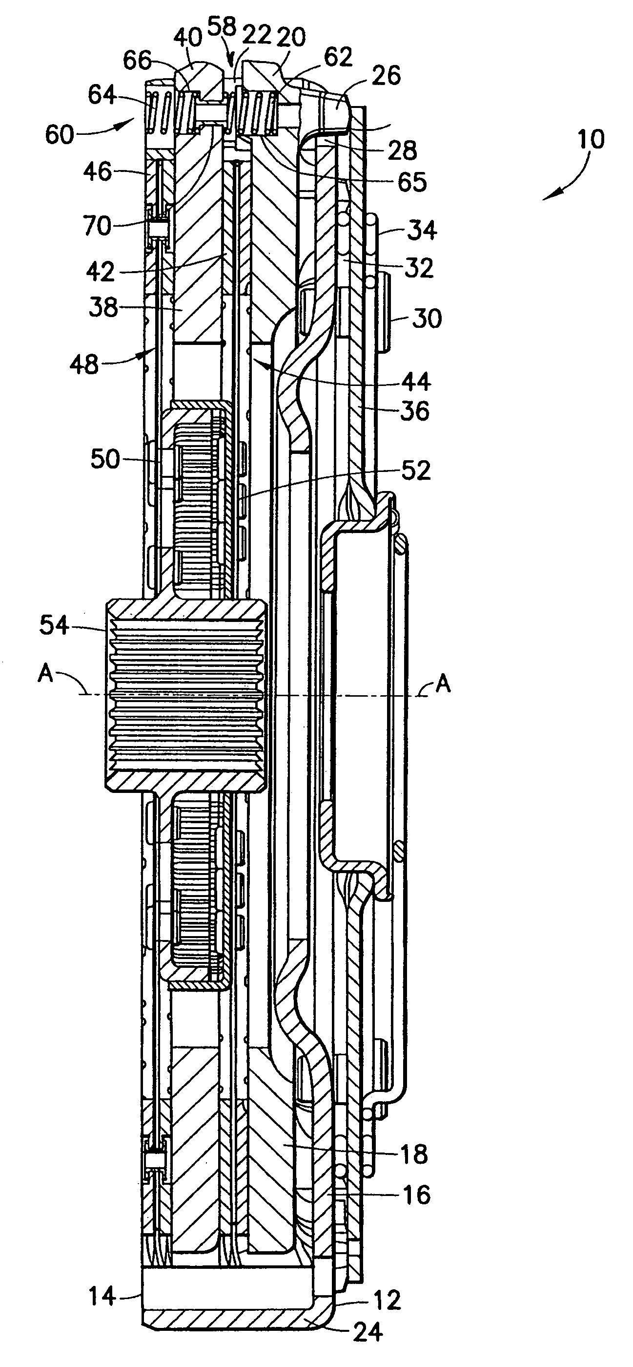
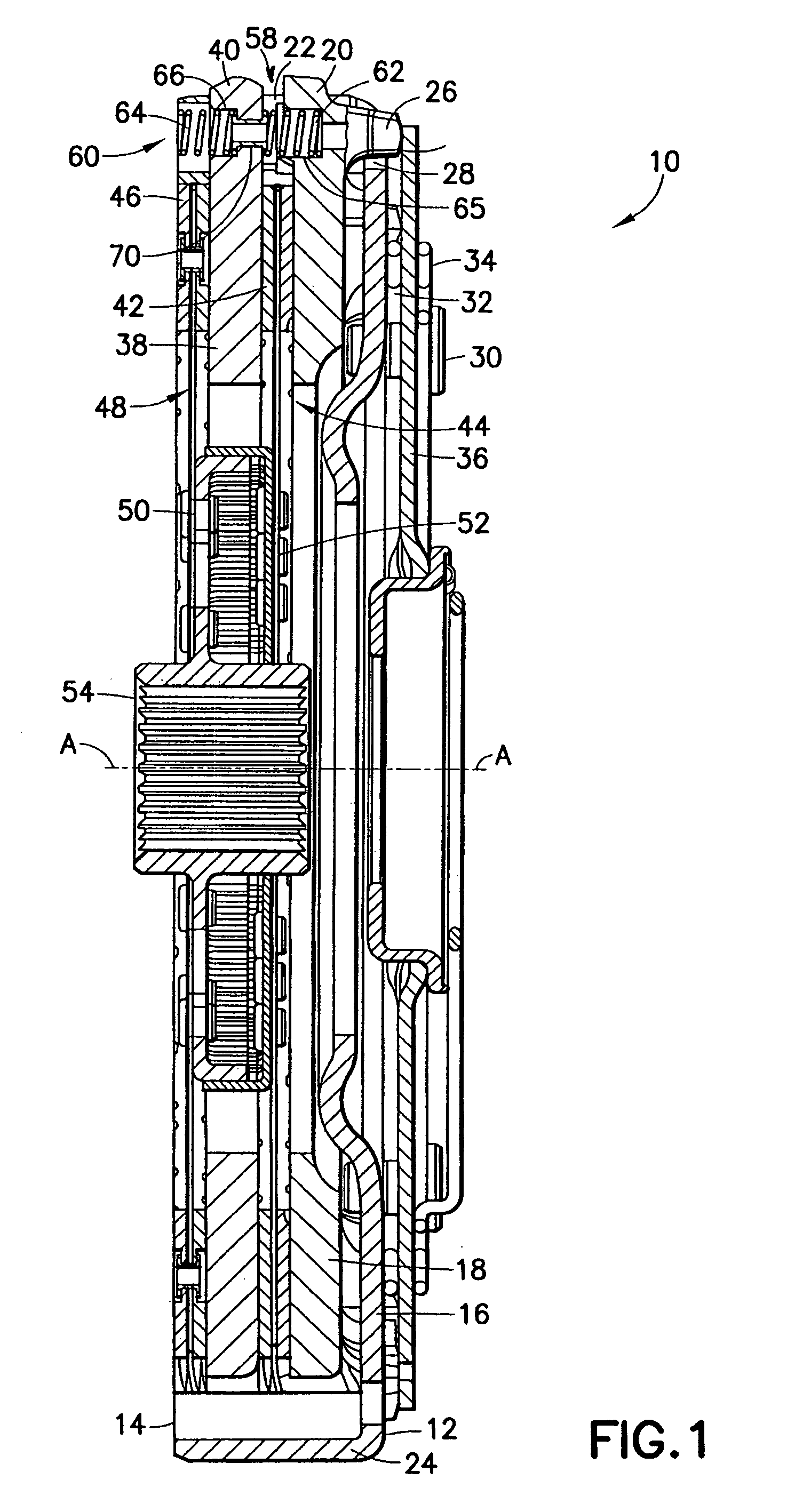
[0022]FIG. 1 shows a longitudinal cross section through a pressure plate assembly 10 for a dual-disk friction clutch, the section being made along the axis of rotation. The pressure plate assembly 10 comprises a pot-like housing 12, made of metal sheet or plate, for example, which can be attached on one axial side 14 to a flywheel (not shown) to complete a friction clutch and which, on the other axial side, has a ring-like bottom area 16. In the space enclosed by the housing 12, there is a pressure plate 18 with a ring-like shape. The pressure plate 18 has radial projections 20 at several points around the circumference so that the plate can be connected to the housing 12 for rotation in common; these projections engage in associated openings 22 in the section 24 of the housing 12, which extends essentially in the axial direction. In this way, the pressure plate 20 is connected to the housing 12 for rotation in common around the axis A, but is still free to shift relative to the hou...


PUM


Abstract

A housing arrangement can be connected to a flywheel for rotation in common around an axis of rotation, and a pressure element is connected to the housing arrangement for rotation in common around the axis of rotation but is able to shift in the axial direction. A release spring arrangement includes at least one spring element which acts on the pressure element and is supported against the flywheel after the housing arrangement has been attached to the flywheel. Each spring element is held in place on the pressure element by means of a fastening element.

Description

BACKGROUND OF THE INVENTION[0001]1. Field of the Invention[0002]The present invention pertains to a pressure plate assembly for a friction clutch, comprising a housing arrangement, which is or can be connected to a flywheel for rotation in common around an axis of rotation; a pressure element, which is connected to the housing arrangement for rotation in common around the axis of rotation and which can shift in the axial direction; and a release spring arrangement, comprising at least one spring element, which acts on the pressure element and is supported against the flywheel after the housing arrangement has been attached to the flywheel.[0003]2. Description of the Related Art[0004]These types of pressure plate assemblies, which can also be designed, for example, as pressure plate assemblies for multi-disk clutches, are usually delivered by the manufacturer in a state in which the pressure plate assembly is not attached to the flywheel or the like. This results in the problem that ...

Claims


Application Information

Patent Timeline
Patent Type & Authority Patents(United States)
IPC IPC(8): F16D13/69F16D13/38F16D13/71
CPCF16D13/71F16D13/385
Inventor SCHAUER, ALFREDKUHN, BERNDSCHUBERT, THOMASPFEIFER, JURGEN
Owner ZF SACHS AG
Why Eureka
Try Eureka