Electronic product
An electronic product, one-to-one correspondence technology, applied to the structure of telephones, etc., can solve the problems of large center-to-center spacing of sound sensor units, increased product production costs, and complicated circuit layout, and achieve the effect of sound hole spacing
- Summary
- Abstract
- Description
- Claims
- Application Information
AI Technical Summary
Problems solved by technology
Method used
Image

Examples
Embodiment 1
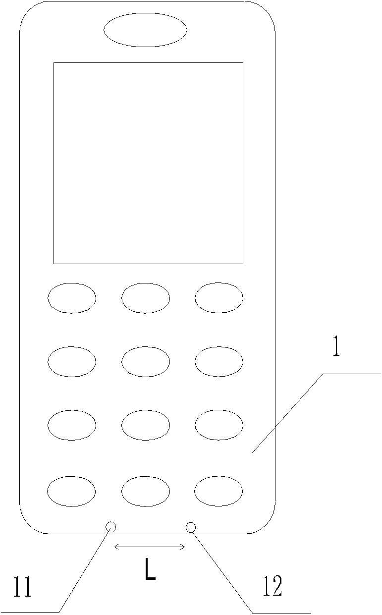
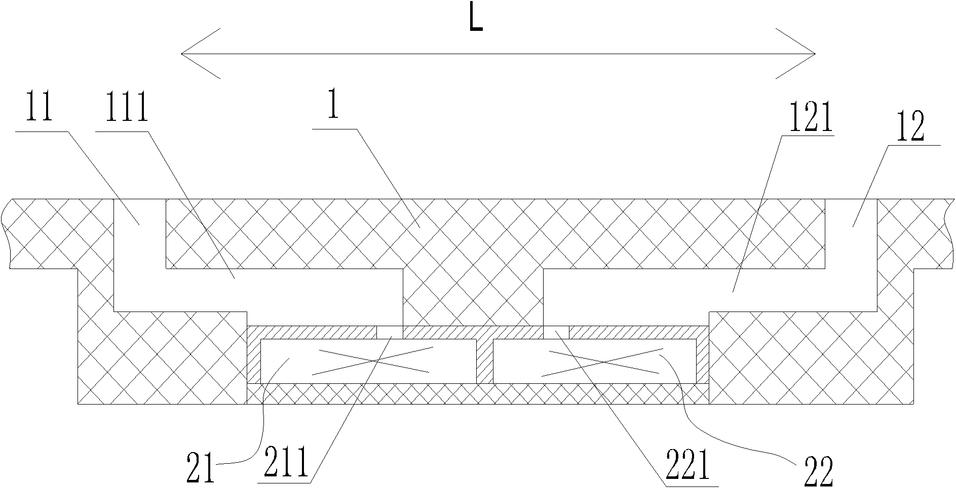
[0039] An example of this embodiment uses a mobile phone as an exemplary carrier of the electronic product of the present invention, figure 1 It is a schematic diagram of the appearance of a mobile phone applying Embodiment 1 of the present invention, Figure 2a for figure 1 The schematic diagram of the local structure at the sound hole of the mobile phone shown.
[0040] Such as figure 1 As shown, 1 is the shell of the mobile phone. Two sound holes 11 and 12 for receiving external sound signals are arranged on the shell 1. The distance L between the sound holes 11 and 12 is greater than 10mm, so that the The received sound signal can have enough phase difference, so as to realize the effect required by the array microphone. exist figure 1 In , there is no detailed description of the internal structure of the sound sensor, only the installation position is indicated.
[0041] Figure 2a It is a schematic diagram of the structure of the part of the mobile phone provided w...
Embodiment 2
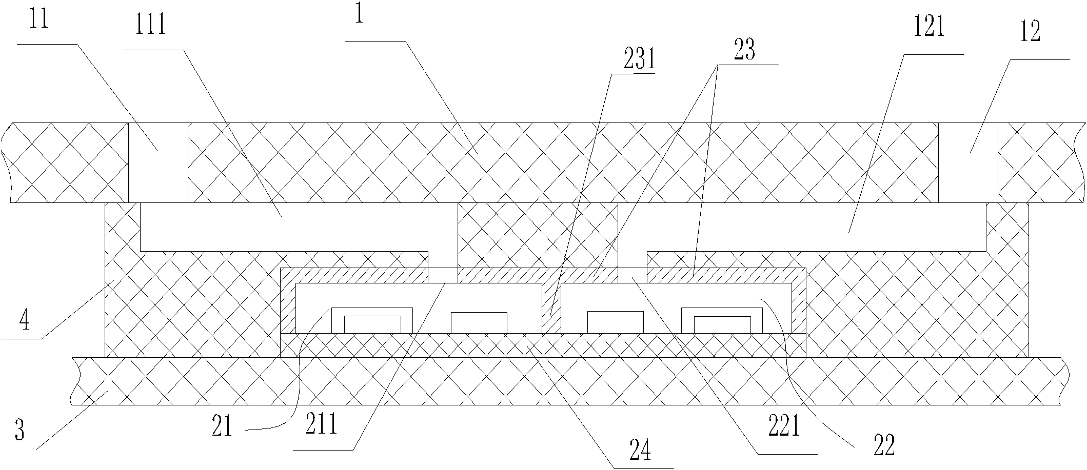
[0051] image 3 It is a partial structural schematic diagram of Embodiment 2 of the present invention. Such as image 3 As shown, with respect to embodiment one, the sound sensor structure and the sound channel structure in the present embodiment two are different, and in the present embodiment two, the sound sensor 21 and the sound sensor 22 are the MEMS sound sensor that utilizes microelectromechanical system technology to make, And be integrated in a package that is made of sound sensor shell 23 and sound sensor circuit board 24, sound sensor shell 23 and sound sensor circuit board 24 combine to form a cavity, MEMS sensor chip 212 and MEMS sensor chip 222 are installed in the Acoustic sensor sound holes 211 and 221 for receiving external sound signals are also provided on the surface of the acoustic sensor circuit board 24 in the cavity, and at positions corresponding to the MEMS sensor chip 212 and the MEMS sensor chip 222 on the acoustic sensor circuit board 24 . Sound ...
Embodiment 3
[0054] Figure 4 It is a partial structural schematic diagram of Embodiment 3 of the present invention. Such as Figure 4 As shown, with respect to embodiment two, the structure of the sound channel in the present embodiment three is different. In the present embodiment three, the flexible rubber sleeve 4 that is provided between the main circuit board 3 of the mobile phone and the shell 1 forms two parallel rubber sleeves inside. The sound holes 41 and 42 are respectively connected to the sound holes 31 and 32 of the main circuit board. The mobile phone casing 1 is provided with two sound channels 111 and 121 which are relatively diffused and extended. The sound channel 111 is respectively connected to the sound hole 11 and the rubber sleeve sound hole 41. The sound channel 121 communicates with the sound hole 12 and the rubber sleeve sound hole 42 respectively. Thereby, the external sound signal can enter from sound hole 11, enter sound sensor 21 and act on MEMS sensor chi...
PUM
 Abstract
Description
Claims
Application Information
 - R&D
- Intellectual Property
- Life Sciences
- Materials
- Tech Scout
- Unparalleled Data Quality
- Higher Quality Content
- 60% Fewer Hallucinations
Browse by: Latest US Patents, China's latest patents, Technical Efficacy Thesaurus, Application Domain, Technology Topic, Popular Technical Reports.
© 2025 PatSnap. All rights reserved.Legal|Privacy policy|Modern Slavery Act Transparency Statement|Sitemap|About US| Contact US: help@patsnap.com