
Top cutting pressure relief equipment and top cutting pressure relief method

A technology of roof cutting, pressure relief and equipment, which is applied in earth square drilling, ground mining, underground mining, etc., which can solve the problems of large space occupation, low work efficiency, and many personnel, and achieve small space occupation, few personnel, and improved work efficiency. efficiency effect

Pending Publication Date: 2022-07-22
SHENHUA SHENDONG COAL GRP +1
View PDF0 Cites 0 Cited by
  • Summary
  • Abstract
  • Description
  • Claims
  • Application Information

AI Technical Summary

Problems solved by technology

The current roof cutting and pressure relief equipment can only cut and relieve pressure in one direction of the rock formation in a single operation, resulting in insignificant pressure relief effect
If it is necessary to cut and relieve the pressure in two vertical directions of the rock formation, it is necessary to use two sets of top cutting and pressure relief equipment for alternate operations, which takes up a lot of space, requires many personnel, and has low work efficiency.

Method used


Image

  • Top cutting pressure relief equipment and top cutting pressure relief method
  • Top cutting pressure relief equipment and top cutting pressure relief method
  • Top cutting pressure relief equipment and top cutting pressure relief method

Examples


Embodiment Construction

[0057] The specific embodiments of the present invention will be further described below with reference to the accompanying drawings. Wherein the same parts are denoted by the same reference numerals. It should be noted that the words "front", "rear", "left", "right", "upper" and "lower" used in the following description refer to the directions in the drawings, and the words "inner" and "outer" ” refer to directions towards or away from the geometric center of a particular part, respectively.

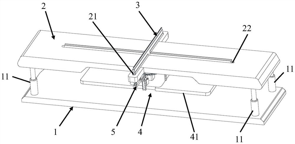
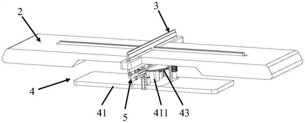
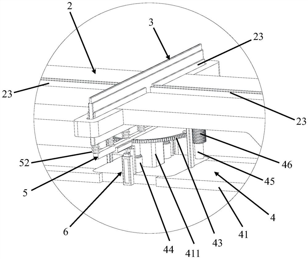
[0058] like Figure 1-5As shown, the top cutting and pressure relief device provided by an embodiment of the present invention includes a base 1 , a lifting top plate 2 , a blade plate 3 and a lifting and rotating drive mechanism 4 for driving the blade plate 3 to lift and rotate.

[0059] A first oil cylinder 11 is connected between the lift top plate 2 and the base 1. The lift top plate 2 has a first through hole 21 and a second through hole 22 for the blade 3 to pass through. The s...


PUM


Abstract

The invention discloses top cutting pressure relief equipment and a top cutting pressure relief method.The top cutting pressure relief equipment comprises a base, a lifting top plate, a cutting board and a lifting rotation driving mechanism used for driving the cutting board to ascend and descend and rotate, the lifting rotation driving mechanism drives the cutting board to rotate and ascend, and the cutting board can selectively stretch out of a first through opening and a second through opening of the lifting top plate; the rock stratum can be subjected to two-way cutting and pressure relief at the same position by adopting one set of top cutting and pressure relief equipment, the occupied space is small, the number of needed personnel is small, and the working efficiency is improved.

Description

technical field [0001] The invention relates to the technical field of mining, in particular to a roof cutting pressure relief device and a roof cutting pressure relief method. Background technique [0002] Coal mines are areas where humans mine coal resources in coal-rich mining areas, and are generally divided into underground coal mines and open pit coal mines. When the distance between the coal seam and the surface is very close, it is generally chosen to directly strip the surface soil layer to excavate the coal, which is an open-pit coal mine. When the coal seam is far from the surface, it is generally chosen to dig underground tunnels to mine coal, which is an underground coal mine. [0003] In the mining process of underground coal mines, it is necessary to cut the top of the rock formation to relieve pressure. The current top cutting and pressure relief equipment can only perform cutting and pressure relief operations in one direction of the rock formation in a si...

Claims


Application Information

Patent Timeline
IPC IPC(8): E21C41/18
CPCE21C41/18
Inventor 杨真王宏建彭德军
Owner SHENHUA SHENDONG COAL GRP
Learn More