
Inner folding hinge structure

A technology of folding hinges and hinges, which is applied in the field of hinges, can solve problems such as the inability to close the door, inconvenient installation, and affect the opening and closing of the door, so as to save replacement costs, save disassembly time, and improve convenience.

Pending Publication Date: 2022-07-22
广东硕维亚科技有限公司
View PDF0 Cites 0 Cited by
  • Summary
  • Abstract
  • Description
  • Claims
  • Application Information

AI Technical Summary

Problems solved by technology

[0004] Hinges are generally connected to the door during use, and the hinges are generally exposed to the outside, but due to the process of being exposed to the outside, the hinges are susceptible to rust due to the influence of the external environment, resulting in accelerated aging of the hinges, and generally The hinges are all in one piece, which is inconvenient to install. At the same time, due to the different proficiency of the installers, sometimes there may be a certain deviation during the installation process, which will cause the door to fail to close or the door to tilt after the hinge is installed, which will affect the door. At the same time, the adjustment needs to disassemble the hinge again, which is very troublesome

Method used


Image

  • Inner folding hinge structure
  • Inner folding hinge structure
  • Inner folding hinge structure

Examples


Embodiment 1

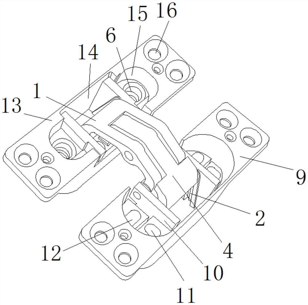
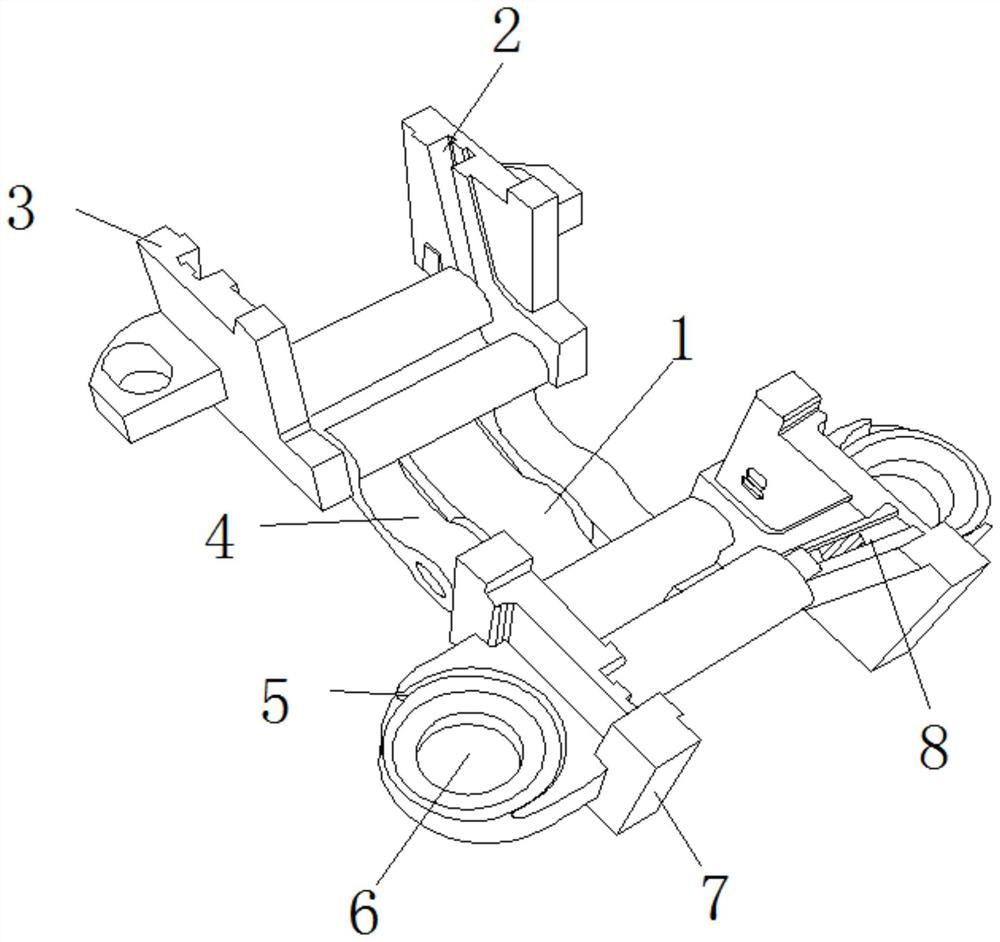
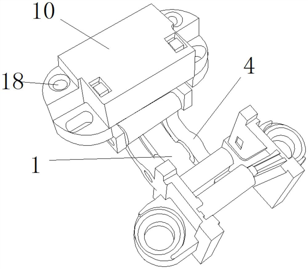
[0034] Example 1, as Figure 1-5 As shown, in the process of assembling the hinge, first install the rocker arm A1 inside the chute C8, install the rocker arm B4 inside the chute A2, and then install the housing 10 between the two sets of connecting plates A3, and Screw the bolt into the fixing hole B18 to connect the housing 10 with the chute A2, put the housing 10 into the storage compartment A9 and tighten the screw, then screw the screw into the adjusting hole A6 to make the sliding The slot B7 is connected to the storage bin B13. At this time, make holes on the door frame and the door leaf. At the same time, install the storage bin B13 on the door leaf, and install the storage bin A9 on the door frame. Finally, screw the screws into the inside of the lock hole 16. , and then fix the placement bin A9 and the placement bin B13.

Embodiment 2

[0035] Example 2, as Figure 1-5 As shown in the figure, when the door gap for installing the door leaf is too large, rotate the bolt inside the adjustment hole A6, and then adjust the front and rear of the door leaf, and then adjust the size of the door gap to prevent the door from being unable to close normally. When the installed door is inclined, Loosen the bolts inside the adjustment hole B11 and the adjustment hole C12, and pull out or push the housing 10 to adjust the left and right of the door leaf. When the adjustment is completed, lock the bolts, and finally open and close the door leaf repeatedly for testing. , and when the door leaf is closed, the rocker arm A1 and the rocker arm B4 slide inside the chute C8 respectively. When the door leaf is completely closed, the rocker arm A1 and the rocker arm B4 will be pushed into the storage compartment B13 and the storage compartment A9. The interior is hidden to prevent it from contacting the outside world.

[0036] Work...


PUM


Abstract

The invention discloses an inner folding hinge structure which comprises a rocker arm A. A rocker arm B is hinged to one side of the rocker arm A. A sliding groove B is formed in one side of the rocker arm A. Fixing blocks are symmetrically arranged on the two sides of the sliding groove B. Adjusting holes A are formed in the tops of the fixing blocks. A connecting plate A is arranged on the side, provided with the rocker arm B, of the outer side of the sliding groove B. Through cooperation of the adjusting hole A, the adjusting hole B and the adjusting hole C, after the door leaf deviates, the position of the door leaf can be adjusted on the premise that the hinge is not disassembled again, then convenience is effectively improved, the disassembling time is saved, and through cooperation of the connecting plate A, the sliding groove B, the shell, the groove B, the containing bin B and the containing bin A, the door leaf can be conveniently disassembled. The hinge can be disassembled into a plurality of parts, subsequent assembly of the hinge is facilitated, when one part in the hinge is damaged, the whole hinge does not need to be replaced, and therefore the replacement cost is saved.

Description

technical field [0001] The invention relates to the technical field of hinges, in particular to an inner folding hinge structure. Background technique [0002] A hinge is a mechanical device used to connect two solids and allow relative rotation between the two. The hinge can be composed of movable components or foldable materials, and is generally used on doors to control the door. opening and closing. [0003] The current hinge, has the following inconveniences: [0004] The hinge is generally connected to the door in the process of use, and the hinge is generally exposed to the outside, but due to the process of exposure to the outside, the hinge is easily affected by the external environment and rusted, resulting in accelerated aging of the hinge, and generally The hinges are all integrated, which is inconvenient to install. At the same time, due to the different proficiency of the installers, sometimes there may be a certain deviation during the installation process, ...

Claims


Application Information

Patent Timeline
IPC IPC(8): E05D7/04E05D3/06E05D5/02
CPCE05D7/04E05D3/06E05D5/02
Inventor 李强李国远
Owner 广东硕维亚科技有限公司
Learn More