Non-clogging aerator and aeration system for sewage treatment or river pollution treatment
A technology for pollution control and sewage treatment, applied in water/sewage treatment, water/sewage multi-stage treatment, water/sludge/sewage treatment, etc. Improve the effect of sewage treatment and improve the effect of fixing effect
- Summary
- Abstract
- Description
- Claims
- Application Information
AI Technical Summary
Problems solved by technology
Method used
Image
Examples
Embodiment 1
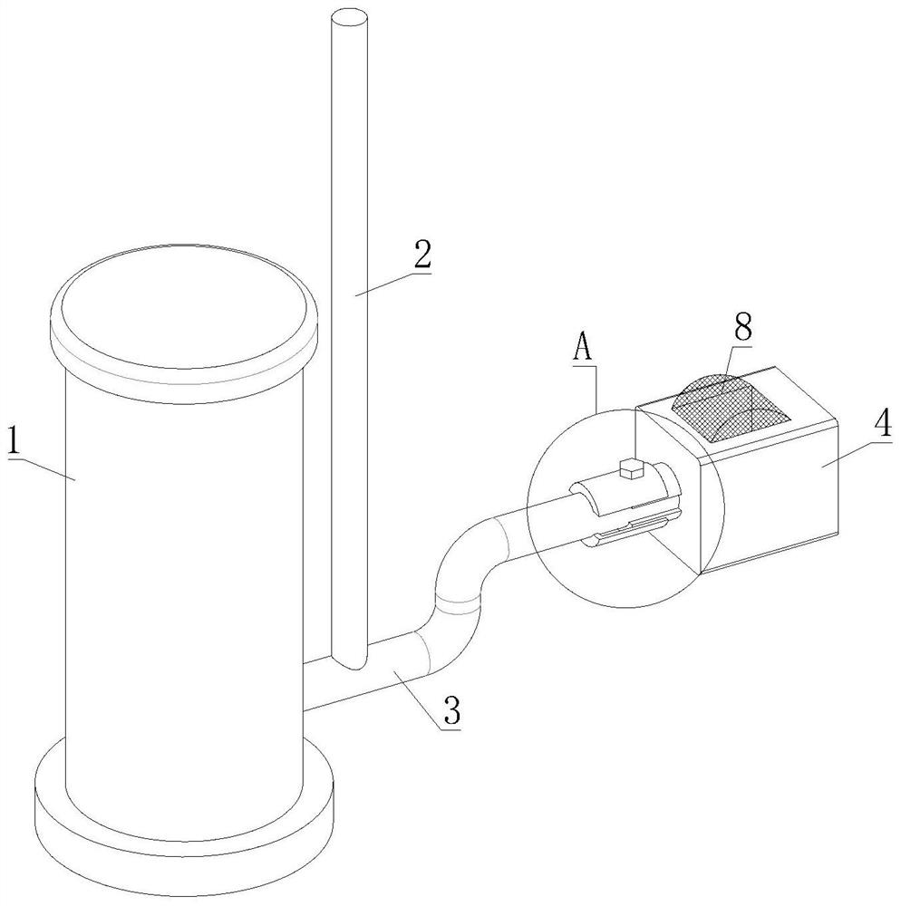
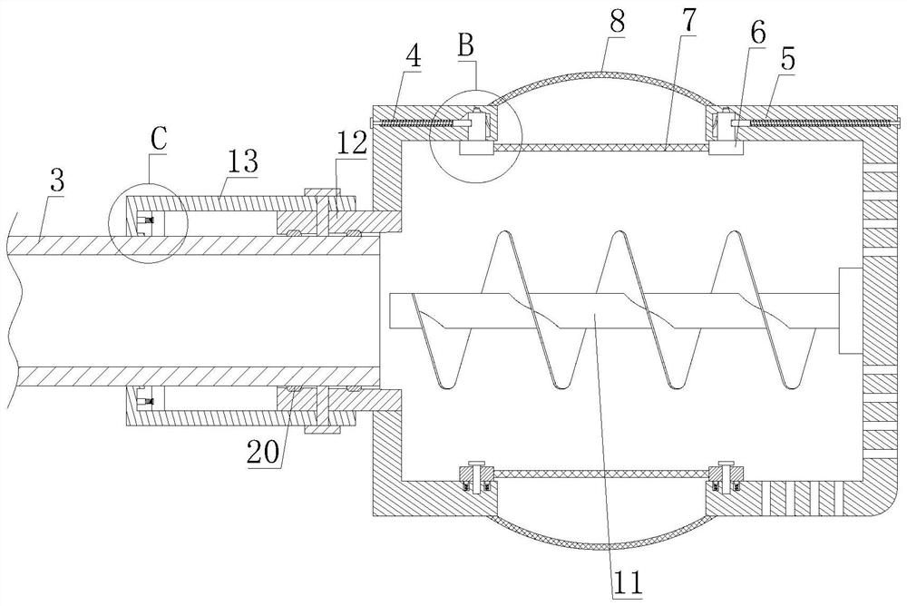
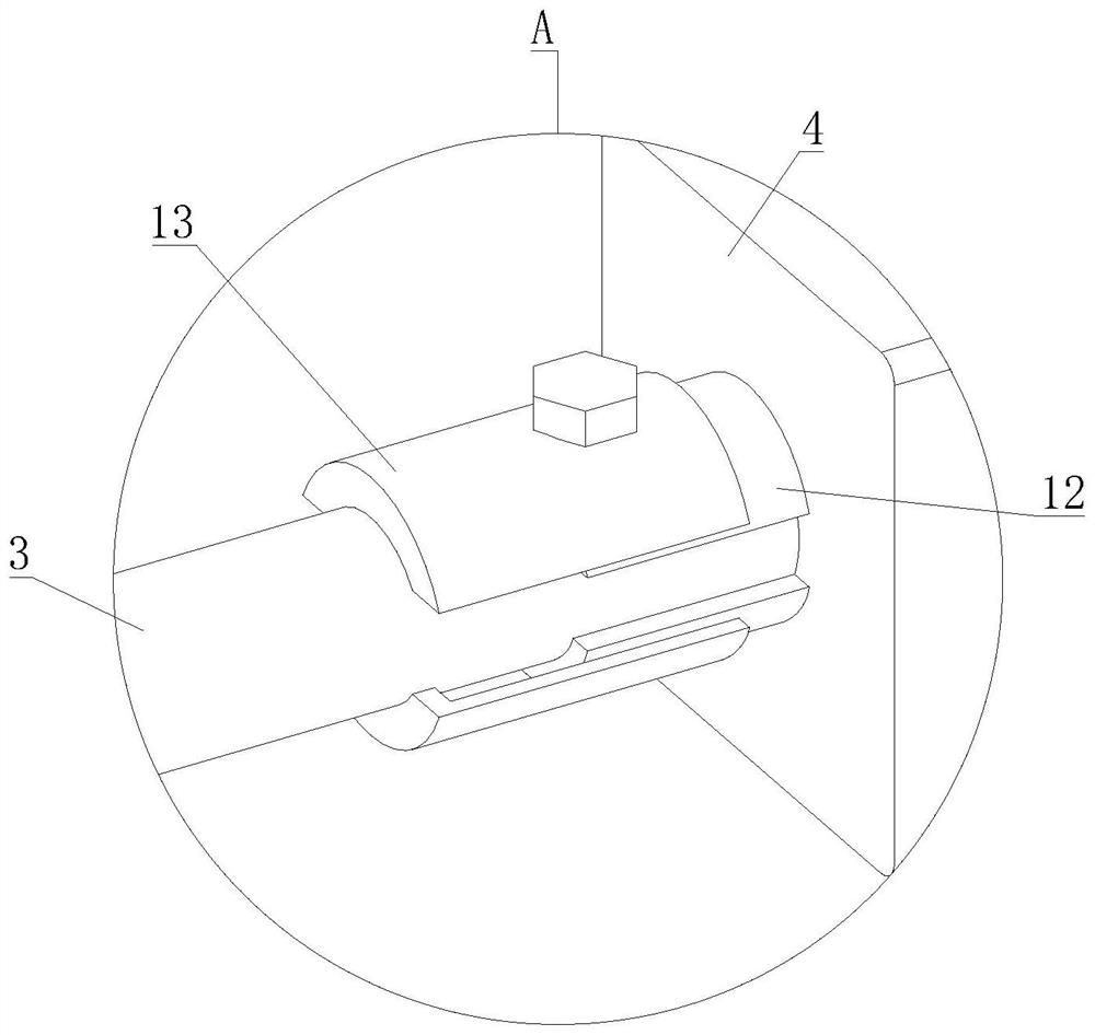
[0028] see Figure 1-7 As shown in the figure, a non-blocking aerator and aeration system for sewage treatment or river pollution control, including an adjustment tank 21 and an aerobic tank 22 arranged on one side of the adjustment tank 21, one side of the aerobic tank 22 is arranged There is an anaerobic tank 23, one side of the anaerobic tank 23 is provided with a sedimentation tank 24, one side of the sedimentation tank 24 is provided with a disinfection tank 25, and the inside of the anaerobic tank 23 is provided with an aerator body 1 , the air outlet duct 3 on the surface of the aerator body 1, the upper end of the air outlet duct 3 is fixed with an air inlet duct 2, and the end of the air outlet duct 3 is installed with a protective casing 4, the protective casing 4 and The air outlet pipes 3 are connected by a connecting plate 12, the connection plate 12 and the protective casing 4 are fixedly connected, the connecting plate 12 and the air outlet pipe 3 are connected ...
Embodiment 2
[0039] see Figure 8 As shown, Comparative Example 1, as another embodiment of the present invention, wherein the limit rod 19 is fixed on the surface of the buffer column 15, and the No. 2 buffer spring 16 is sleeved on the surface of the limit rod 19; The limit rod 19 can limit the position of the buffer column 15 , thereby preventing the No. 2 buffer spring 16 from being deformed when the force is too large.
[0040] Working principle, when the sewage is aerated, the medicine is first put into the interior of the No. 2 intercepting net 8, and then the fixing column 93 is pulled first, and then the fixing strip 91 on the surface of the installation frame 6 and the inner wall of the protective shell 4 are connected. The mounting grooves 94 are connected correspondingly, and then the fixing column 93 is loosened, and the fixing column 93 is located inside the fixing groove 92 by using the characteristics of the fixing spring 95, so as to fix the mounting frame 6, so that the m...
PUM
 Abstract
Description
Claims
Application Information
 - R&D
- Intellectual Property
- Life Sciences
- Materials
- Tech Scout
- Unparalleled Data Quality
- Higher Quality Content
- 60% Fewer Hallucinations
Browse by: Latest US Patents, China's latest patents, Technical Efficacy Thesaurus, Application Domain, Technology Topic, Popular Technical Reports.
© 2025 PatSnap. All rights reserved.Legal|Privacy policy|Modern Slavery Act Transparency Statement|Sitemap|About US| Contact US: help@patsnap.com


