EBS shaft module pressure control method based on high-frequency PWM

A technology of pressure control and shaft module, which is applied in the direction of brakes, brake transmission devices, vehicle components, etc., can solve the problems of large overshoot, low control precision, and poor brake pedal feel, and achieve shortened braking distance and reduced The effect of long decompression process and avoiding overshoot

Pending Publication Date: 2022-07-22
BEIJING JINWANAN AUTOMOBILE ELECTRONICS TECH RES
View PDF1 Cites 0 Cited by
  • Summary
  • Abstract
  • Description
  • Claims
  • Application Information

AI Technical Summary

Problems solved by technology

At the same time, because the switch solenoid valve only has two states of on and off, the flow adjustment function of the proportional solenoid valve cannot be realized, so in the pressure control of the brake chamber, there are low control accuracy, large overshoot, and poor brake pedal feel. , severe fever, etc.
[0004] At present, there are also some high-speed switching solenoid valve pressure control methods based on high-frequency PWM, but most of them are aimed at hydraulic systems. Patent authorization number CN105889603B and application number 201610356795.9 disclose a PWM control method for improving the proportional characteristics of high-speed switching solenoid valves. Improve the proportional control range of the flow rate and pressure controlled by the high-speed switching solenoid valve, and realize the fine adjustment of the opening of the valve port. However, this method is aimed at the hydraulic high-speed switching solenoid valve, and does not consider the pressure difference between the inlet and outlet of the solenoid valve on the valve core. Effect of opening

Method used


Image

  • EBS shaft module pressure control method based on high-frequency PWM
  • EBS shaft module pressure control method based on high-frequency PWM
  • EBS shaft module pressure control method based on high-frequency PWM

Examples


Embodiment 1

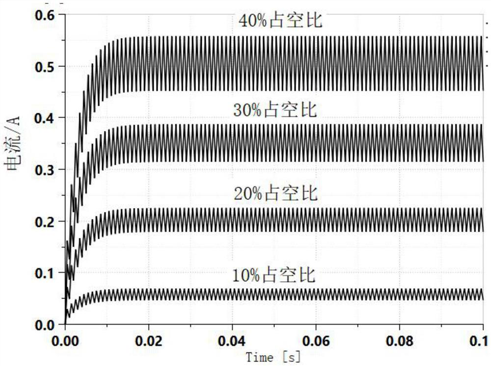
[0037] The invention provides an EBS shaft module pressure control method based on high-frequency PWM. The method realizes switching of the solenoid valve by adjusting the duty ratio of the high-frequency PWM signal and simultaneously considering the influence of the inlet and outlet pressure difference on the valve core opening. It has the function of flow regulation to achieve the purpose of accurately controlling the pressure of the brake air chamber.

[0038] The control method is realized through the following steps:

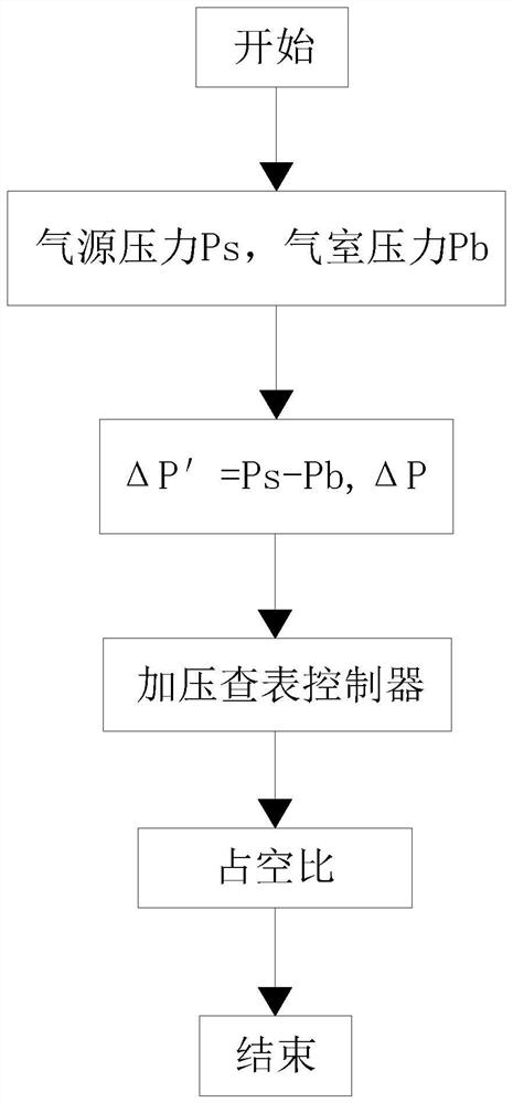
[0039] First collect the target pressure value P output by the foot brake valve t and the current actual pressure P output by the brake chamber pressure sensor b , the difference between the two is used to calculate the pressure difference ΔP.

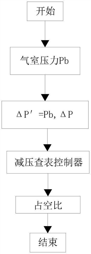
[0040] According to the calculated differential pressure ΔP, determine the state that the axis module needs to enter. When ΔP≥0.1bar, the axis module enters the pressurized control state, and outputs a high-frequenc...


PUM


Abstract

The invention relates to the field of automobile brake system control, and discloses an EBS shaft module pressure control method based on high-frequency PWM, which comprises the following steps of: 1, acquiring a target pressure value Pt output by a foot brake valve and a current actual pressure Pb output by a brake chamber pressure sensor, and calculating a pressure difference delta P by taking a difference value between the target pressure value Pt and the current actual pressure Pb; 2, according to the pressure difference delta P obtained through calculation, the state in which the shaft module needs to enter is judged, and when delta P is larger than or equal to 0.1 bar, the shaft module enters the pressurization control state; when delta P is smaller than or equal to-0.1 bar, the shaft module enters a decompression control state, and when delta P is-0.1 bar; [delta] Plt; and when the voltage is 0.1 bar, the shaft module is in a pressure maintaining state, and the pressurizing/depressurizing electromagnetic valve does not act. According to the method, by adjusting the duty ratio of the high-frequency PWM signal, the driving current of the electromagnetic valve can be changed, the electromagnetic valve element is made to be in the middle position of the on-off state, the opening degree of the electromagnetic valve element can be dynamically adjusted, fine adjustment of the pressure of the brake chamber is achieved, the pressure control precision is improved, the response speed is increased, and overshoot is reduced.

Description

technical field [0001] The invention belongs to the field of vehicle braking system control, and in particular relates to a high-frequency PWM-based EBS shaft module pressure control method. Background technique [0002] The Electronically Controlled Brake System (EBS) is developed on the ABS anti-lock braking system. Compared with the conventional braking system, the commercial vehicle EBS adopts the electronically controlled air brake, which can achieve faster braking. Dynamic response time, more reasonable braking force distribution, and more comprehensive braking system control can effectively improve the braking efficiency of the vehicle and greatly improve the safety and comfort of the vehicle driver. Based on EBS, a variety of system functions can also be expanded, such as vehicle stability control (ESC), adaptive cruise (ACC), automatic emergency braking (AEB) and other functions. [0003] In the current electric control brake system (EBS) of commercial vehicles, th...

Claims


Application Information

Patent Timeline
Patent Type & Authority Applications(China)
IPC IPC(8): B60T13/74B60T13/68B60T8/36
CPCB60T13/74B60T13/683B60T8/3655
Inventor 陈锋付德春刘世超姜丹娜任超
Owner BEIJING JINWANAN AUTOMOBILE ELECTRONICS TECH RES
Why Eureka
Try Eureka