


Quick Research
Generate reliable direction feasibility study reports for your R&D in just a few steps.

Technical Q&A
Discover and master advanced knowledge NOW. Basics, ideas, possibilities, all at once.

Find Solutions
As an expert in R&D theories, this can generate solutions to your technical problems instantly.

Evaluate Feasibility
Analyze your overall solution with one click, know your potential R&D risks in advance.

Monitor Landscape
Get weekly tech updates, stay abreast of the latest tech innovations and key insights.
Double-end butt joint processing machine tool
A processing machine tool and double-head technology, which is applied in the direction of metal processing machinery parts, metal processing equipment, manufacturing tools, etc., can solve the problems that affect the processing accuracy, reduce the quality of parts, and the parts are prone to displacement, so as to improve the quality of docking and smooth processing , Improve the effect of machining accuracy
- Summary
- Abstract
- Description
- Claims
- Application Information
AI Technical Summary
Problems solved by technology
Method used
Image


Examples
Embodiment 1
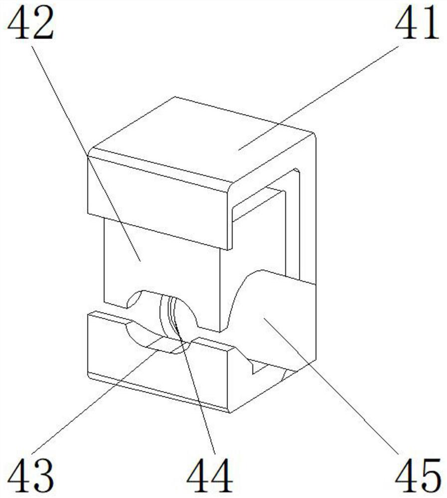
[0027] like Figure 1-5 As shown, the present invention provides a double-head butt processing machine tool, comprising a main body 1, a damping device 2 is arranged above the main body 1, a clamping mechanism 7 is arranged above the damping device 2, and a clamping mechanism 7 is arranged above There is a pulling shaft 6, one side of the pulling shaft 6 is provided with a second head 8, one side of the second head 8 is provided with a rotating gear 9, the lower end of the rotating gear 9 is provided with a motor 3, and the other side of the pulling shaft 6 is provided A first machine head 5 is provided, and a docking device 4 is provided on one side of the first machine head 5; The groove 42 is located at the concave surface of the concave block 41, and the guide mechanism 45 is located at the lower end of the upper groove 42; a welding block is arranged between the upper groove 42 and the concave block 41, and the upper end of the upper groove 42 passes through the welding b...
Embodiment 2
[0030] like Figure 1-5 As shown, on the basis of Embodiment 1, the present invention provides a technical solution: preferably, the clamping mechanism 7 includes a mounting block 71, an adjusting rod 72, a clamping block 73, a locking bolt 74, a connecting rod 75, and the connecting rod 75 is located at the lower end of the mounting block 71, the locking bolt 74 is located at the lower end of the connecting rod 75, the adjusting rod 72 is located on both sides of the mounting block 71, the clamping block 73 is located at the lower end of the adjusting rod 72, and the adjusting rod 72 and the mounting block 71 are arranged between the There is a fixed plate, the upper end of the adjustment rod 72 is fixedly connected to one side of the installation block 71 through the fixed plate, a movable bolt is arranged between the adjustment rod 72 and the clamping block 73, and the lower end of the adjustment rod 72 passes through the movable bolt and the upper end of the clamping block ...
Embodiment 3
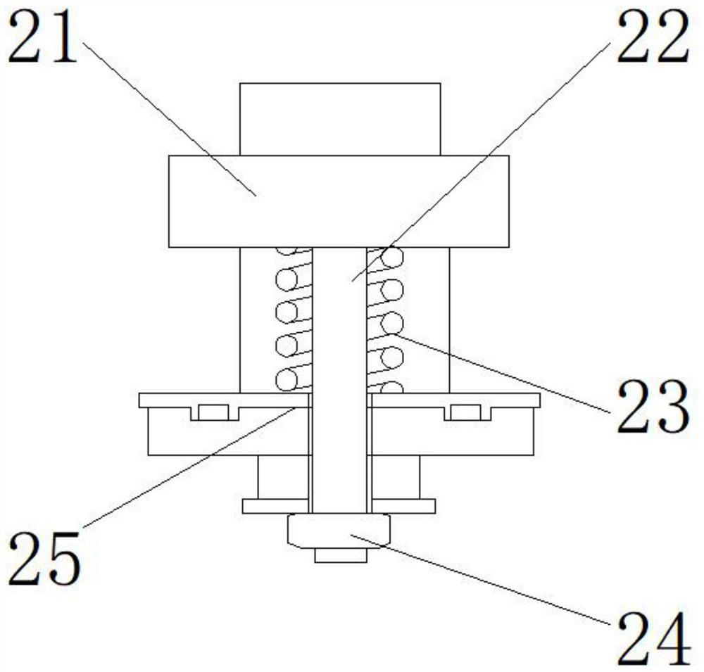
[0033] like Figure 1-5 As shown, on the basis of Embodiment 1, the present invention provides a technical solution: preferably, the damping device 2 includes a spring seat 21, a bearing 22, a damping spring 23, a bolt 24, and a damper 25, and the bearing 22 is located in the spring At the lower end of the seat 21, the shock-absorbing spring 23 is wound on the outer surface of the bearing 22, the damper 25 is located at the lower end of the shock-absorbing spring 23, the bolt 24 is positioned at the lower end of the bearing 22, and an interface is provided between the shock-absorbing spring 23 and the spring seat 21, The lower end of the spring seat 21 is fixedly connected to the upper end of the damping spring 23 through the interface, a threaded groove is provided between the bearing 22 and the spring seat 21, and the upper end of the bearing 22 is detachably connected to the lower end of the spring seat 21 through the threaded groove, and the damper 25 An interface is provi...
PUM
 Abstract
Description
Claims
Application Information
 - R&D Engineer
- R&D Manager
- IP Professional
- Industry Leading Data Capabilities
- Powerful AI technology
- Patent DNA Extraction
Browse by: Latest US Patents, China's latest patents, Technical Efficacy Thesaurus, Application Domain, Technology Topic, Popular Technical Reports.
© 2024 PatSnap. All rights reserved.Legal|Privacy policy|Modern Slavery Act Transparency Statement|Sitemap|About US| Contact US: help@patsnap.com