Variable-frequency and variable-intensity feed vibration cutting and stirring device and method

A technology for vibrating cutting and stirring devices, applied in chemical instruments and methods, transportation and packaging, shaking/oscillating/vibrating mixers, etc. The effect of reducing viscosity, reducing cutting resistance and fast processing

Pending Publication Date: 2022-07-22
SHANDONG AGRICULTURAL UNIVERSITY +1
View PDF0 Cites 0 Cited by
  • Summary
  • Abstract
  • Description
  • Claims
  • Application Information

AI Technical Summary

Problems solved by technology

At present, the feed preparation machine has the disadvantage of time-consuming and energy-consuming mixing and cutting operations, and the helical blades, blades and tanks are seriously worn.

Method used


Image

  • Variable-frequency and variable-intensity feed vibration cutting and stirring device and method
  • Variable-frequency and variable-intensity feed vibration cutting and stirring device and method
  • Variable-frequency and variable-intensity feed vibration cutting and stirring device and method

Examples


Embodiment 1

[0026] like figure 1 A feed vibration cutting and stirring device with variable frequency and intensity is shown, including a tank body 14, a cutting and stirring spindle 17 rotatably connected with the tank body, and a first driving device for driving the rotation of the cutting and stirring spindle, the tank body and the cutting and stirring spindle. The axes of the stirring main shafts are all arranged in the vertical direction to form a vertical structure. A bottom frame 1 is arranged below the tank body, the bottom frame 1 is placed horizontally on the ground, a load cell 12 for weighing the weight of the tank body is fixedly arranged on the bottom frame, and a connecting seat 13 is fixed to the bottom of the tank body. 13 is connected to the load cell 12 fixed on the chassis.

[0027] The first driving device includes a prime mover 2, and a reducer 3 that is connected to the prime mover through a universal joint. The reducer 3 is installed on the chassis 1, and the outp...

Embodiment 2

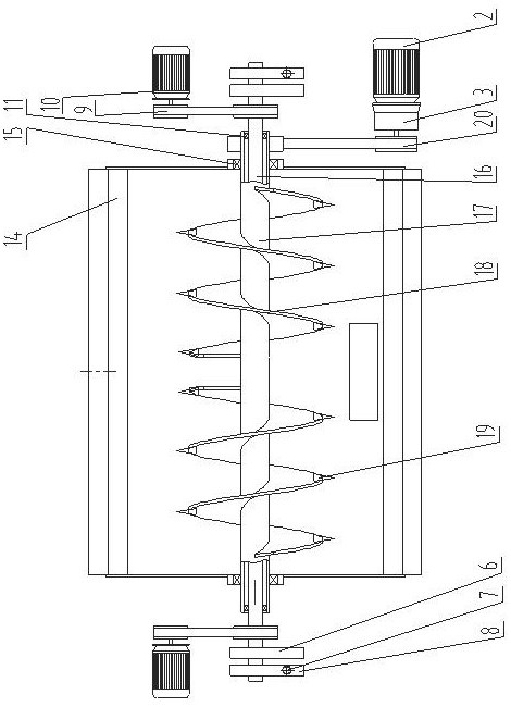
[0038] like image 3 As shown in the figure, the difference between this embodiment and the first embodiment is that the axes of the tank body, the cutting and stirring main shaft and the synchronous transmission shaft in this embodiment are all arranged in the horizontal direction, in a horizontal structure, and the two ends of the cutting and stirring main shaft are respectively horizontal The direction extends out of the tank body, and is respectively connected with the tank body through the bearing group in rotation, so as to improve the balance of the cutting and stirring spindle.

[0039] The prime mover is directly connected to the reducer, the output shaft of the reducer is connected to the cutting and stirring main shaft through the belt II20, and the output shaft of the prime mover and the cutting and stirring main shaft are respectively equipped with pulleys adapted to the belt II20.

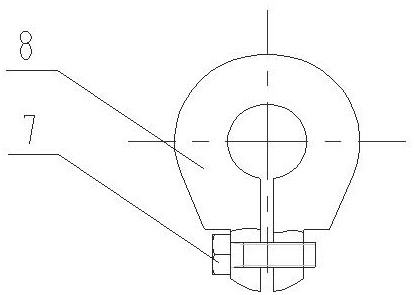
[0040] Frequency conversion motors 10 are respectively arranged on the left and r...


PUM


Abstract

The invention relates to a feed vibration cutting and stirring device and method with variable frequency and strength, the feed vibration cutting and stirring device comprises a tank body, a cutting and stirring main shaft and a first driving device for driving the cutting and stirring main shaft to rotate, and the cutting and stirring main shaft is fixedly provided with a spiral blade located in the tank body; cutting blades are installed on the spiral blades, and a vibration mechanism is further installed on the cutting and stirring main shaft. The vibration intensity and the vibration frequency can be adjusted, so that the proper vibration intensity and frequency can be selected according to specific operation conditions, and feed in the tank body is subjected to vibration cutting and stirring; by means of vibration, cutting resistance between the cutting blades and materials is reduced, friction resistance between the spiral blades and the materials is reduced, viscous force between the materials is reduced, the materials can be mixed and cut rapidly and evenly, and the device has the advantages of being rapid in machining, even in mixing and capable of saving energy. And the abrasion of the spiral blade, the cutting blade and the tank body is reduced.

Description

technical field [0001] The invention relates to the technical field of feed processing machinery, in particular to the cutting and stirring of feed, in particular to a feed vibration cutting and stirring device and method with variable frequency and intensity. Background technique [0002] In the breeding of livestock such as cattle and sheep, roughage, concentrate and other additives need to be mixed evenly in a certain proportion, and the long forage is cut to make a mixed feed with balanced nutrition. A feed preparation machine is a machine for processing feed, with functions such as weighing, cutting, kneading, stirring and mixing. [0003] The stirring and cutting system of the current feed preparation machine is mainly composed of a stirring spindle, a spiral blade and a cutting blade. The stirring spindle drives the spiral blade wound on the main shaft to realize stirring and mixing, and the blade installed on the spiral blade realizes the cutting of long forage. . ...

Claims


Application Information

Patent Timeline
Patent Type & Authority Applications(China)
IPC IPC(8): B01F31/44B01F33/83B01F101/18
Inventor 范国强员荣基孙杰王辛政刘猛董和银
Owner SHANDONG AGRICULTURAL UNIVERSITY
Why Eureka
Try Eureka