
Internal display module of intelligent oven

An internal display and oven technology, which is applied to roasters/barbecue grids, color TV parts, TV system parts, etc., can solve the problem of fogging of the visible window, low image quality, and inability to see the internal situation clearly and other problems, to achieve the effect of isolating the camera from the heat source, improving the shooting effect, and increasing the shooting range

Pending Publication Date: 2022-07-22
广州汇豪计算机科技开发有限公司
View PDF0 Cites 1 Cited by
  • Summary
  • Abstract
  • Description
  • Claims
  • Application Information

AI Technical Summary

Problems solved by technology

The existing oven includes a box body and a box door, wherein a visible window is set on the box door to observe the inside of the box body. The user can start heating the food after manually selecting the heating mode according to the weight, temperature and type of the food material. During the heating process, the food will generate some water vapor, which will cause the visible window to fog up and make it difficult to see the internal situation. At the same time, people cannot obtain the specific temperature of the food. Inappropriate heating mode and temperature will lead to unsatisfactory heating results. In addition, some smart ovens use a camera and a display screen on the box cover to obtain the situation inside the box, but because the camera is not protected, the camera will be damaged in a high-temperature environment and cannot meet people's needs. Demand, even if a glass sheet is added for heat insulation, there will be fogging, and the quality of the shooting image is low

Method used


Image

  • Internal display module of intelligent oven
  • Internal display module of intelligent oven
  • Internal display module of intelligent oven

Examples


Embodiment Construction

[0023] The present invention will now be described in further detail with reference to the accompanying drawings. These drawings are all simplified schematic diagrams, and only illustrate the basic structure of the present invention in a schematic manner, so they only show the structures related to the present invention.

[0024] In the present invention, it should be noted that the orientation or positional relationship indicated by the terms "upper", "lower", "inside", "outside", "between", etc. is based on the orientation or positional relationship shown in the accompanying drawings, It is only for the convenience of describing the present invention and simplifying the description, rather than indicating or implying that the referred device or element must have a specific orientation, be constructed and operated in a specific orientation, and therefore should not be construed as a limitation of the present invention; the term "first" , "Second" is only for the purpose of de...


PUM


Abstract

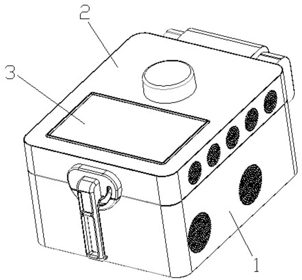
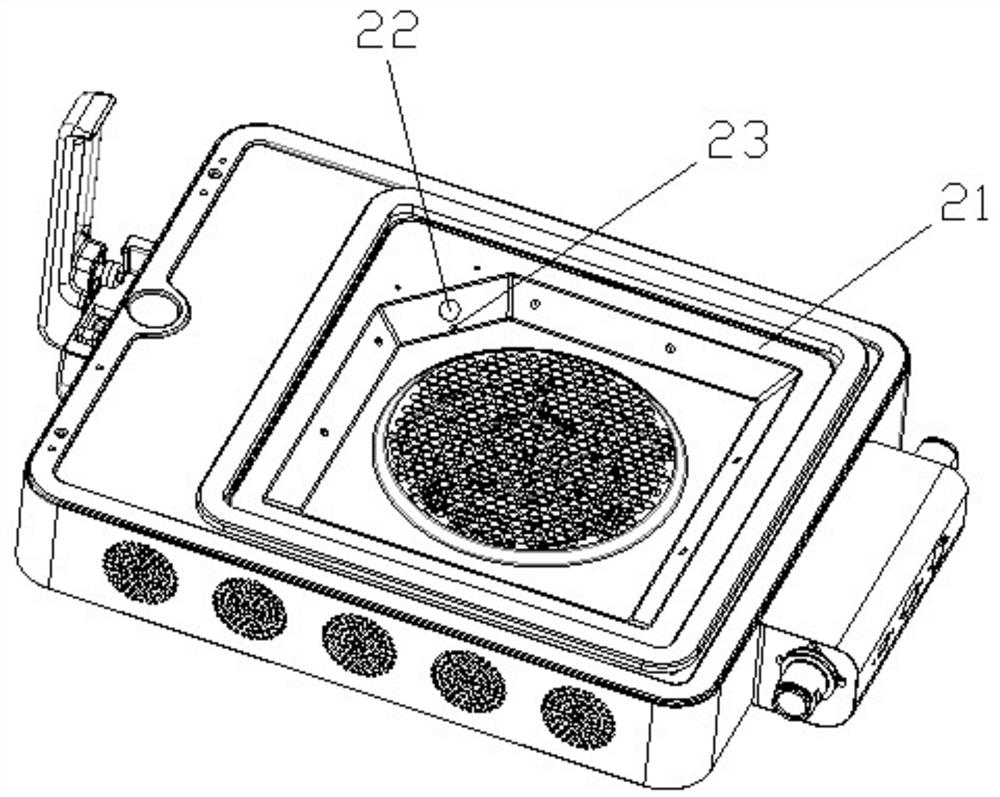
The invention specifically discloses an intelligent oven internal display module which comprises an oven body and an oven cover, a mesh plate is installed on the inner surface of the oven cover, the middle of the mesh plate is sunken towards the interior of the oven cover to form a gradually-shrinking boss, a groove is formed in the edge of the gradually-shrinking boss and the edge of the mesh plate, and a temperature measuring and shooting assembly is arranged in the groove; the temperature measurement shooting assembly comprises a base, one side of the base is provided with an inclined plate, the inclined plate is in lap joint with the side end of the gradually-shrunk boss, the end face, making contact with the gradually-shrunk boss, of the inclined plate is provided with an air flow channel, and the inclined plate is provided with a camera corresponding to the air flow channel. A shooting hole corresponding to the camera is formed in the side edge of the gradually-shrinking boss, and a first glass sheet and a second glass sheet are arranged on the gradually-shrinking boss and located at the two ends of the shooting hole respectively. The camera has the advantages of being easy and convenient to install, free of fogging in the shooting process and high in shooting quality, the camera is isolated from a heat source, and the service life is longer.

Description

technical field [0001] The invention relates to the technical field of intelligent ovens, in particular to an internal display module of an intelligent oven. Background technique [0002] With the accelerated pace of life, the use of ovens is becoming more and more extensive, and users can heat ingredients through various recipes and heating modes. The existing oven includes a box body and a box door. The box door is provided with a visual window to observe the inside of the box body. After the user manually selects the heating mode according to the weight, temperature and type of the food, the food can be heated. During the heating process, the food will generate some water vapor, which will cause the visual window to fog up and make it difficult to see the internal situation. At the same time, people cannot obtain the specific temperature of the food. Inappropriate heating mode and temperature will lead to unsatisfactory heating results. In addition, some smart ovens use ...

Claims


Application Information

Patent Timeline
Patent Type & Authority Applications(China)
IPC IPC(8): A47J37/06H04N5/225
CPCA47J37/0664H04N23/50
Inventor 唐文华
Owner 广州汇豪计算机科技开发有限公司
Learn More