
Pull-type monitoring equipment and nuclear facility

A monitoring equipment and traction-type technology, applied in the field of traction-type monitoring equipment and nuclear facilities, can solve the problems of high radiation risk, inconvenient entry and exit of personnel, and difficulty in installation and maintenance, so as to ensure accuracy, good radiation protection performance, and radiation protection. According to the effect of small risk

Pending Publication Date: 2022-07-15
CHINA NUCLEAR POWER ENG CO LTD
View PDF0 Cites 0 Cited by
  • Summary
  • Abstract
  • Description
  • Claims
  • Application Information

AI Technical Summary

Problems solved by technology

In the past, the radiation level monitoring of such rooms was generally completed through radiation detection instruments arranged in the room. However, due to the high background radiation level in the room, it is inconvenient for personnel to enter and exit the room, and some process equipment Extending downward from the floor of the room, it is difficult to install and maintain, and the risk of radiation exposure is high

Method used


Image

  • Pull-type monitoring equipment and nuclear facility
  • Pull-type monitoring equipment and nuclear facility

Examples


Embodiment 1

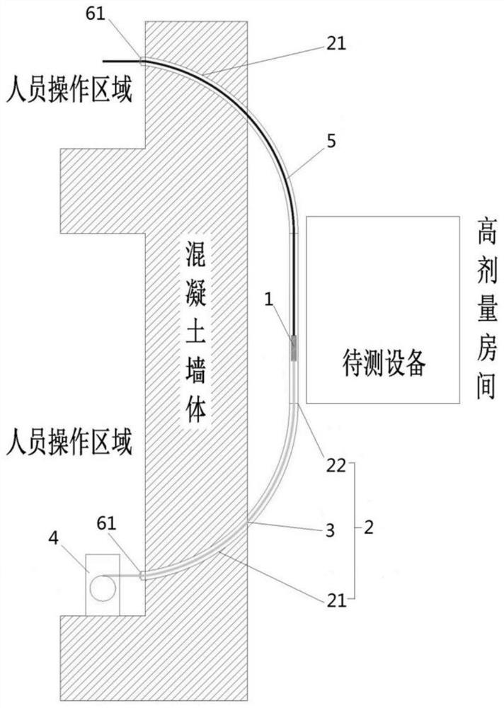
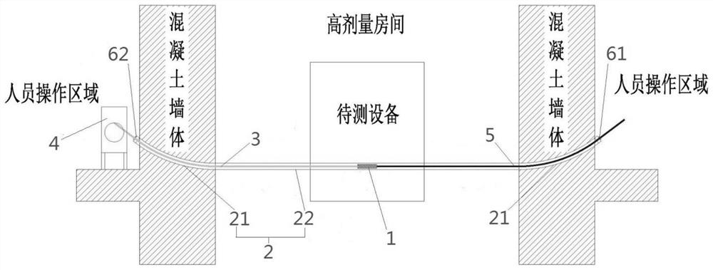
[0027] like figure 1 , figure 2 As shown, the present embodiment discloses a traction type monitoring device, which is used for radiation level monitoring in a high-dose room, which includes a detector 1, a casing 2, and a traction device 4, wherein: the two ends of the casing 2 are respectively threaded On the wall (concrete wall) of the high-dose room, and communicated with the outside of the high-dose room, the other parts of the casing 2 are set inside the high-dose room; the detector 1 is set in the casing 2 and is located in the high-dose room. The interior of the dose room is used to detect the radiation level inside the high-dose room; the pulling device 4 is connected with the detector 1 through the pulling rope 3, and is set in the area outside the high-dose room that is convenient for personnel to operate, for pulling the detector 1 in the The casing 2 is moved inside, so that the detector reaches the preset detection position in the casing.

[0028] During insta...

Embodiment 2

[0044] This embodiment discloses a nuclear facility, including a high-dose room, and the traction type monitoring device described in Embodiment 1. The casing in the traction type monitoring device is passed through the wall (concrete wall) of the high-dose room.

[0045] Specifically, as figure 1 As shown, both ends of the sleeve 2 may be disposed at different heights of the wall in the same direction, and one end is located above the other end, that is, the traction monitoring equipment adopts a longitudinal installation form. like figure 2 As shown, the two ends of the sleeve 2 can also be respectively penetrated on two walls, for example, respectively penetrated on two opposite walls (such as figure 2 shown) or installed on two adjacent walls (not shown in the figure), that is, the traction monitoring equipment adopts the horizontal installation form.


PUM


Abstract

The invention discloses traction type monitoring equipment, which comprises a detector, a sleeve and a traction device, and is characterized in that two ends of the sleeve are respectively arranged on a wall body of a high-dose room in a penetrating manner and are communicated with the outside of the high-dose room, and other parts of the sleeve are arranged in the high-dose room; the detector is arranged in the sleeve, is located in the high-dose room and is used for detecting the radiation level in the high-dose room; the traction device is connected with the detector through a traction rope, is arranged outside the high-dose room and is used for pulling the detector to move in the sleeve, so that the detector reaches a preset detection position in the sleeve. The invention further discloses a nuclear facility. The monitoring equipment is convenient to install and overhaul, and the irradiation risk is small.

Description

technical field [0001] The invention belongs to the field of nuclear technology, and in particular relates to a traction monitoring device and a nuclear facility. Background technique [0002] Generally, there are some rooms in nuclear facilities with high radiation levels. This part of the rooms with high doses of radiation is equipped with a large number of process equipment, and there may be radiation critical risks. The radiation levels in the rooms need to be monitored. In the past, the monitoring of the radiation level of such a room was generally completed by the radiation detection instrument arranged in the room. However, due to the high background radiation level in the room, it was inconvenient for personnel to enter and leave the room, and some process equipment It is arranged extending downward from the floor of the room, which is difficult to install and maintain, and the risk of irradiation is high. SUMMARY OF THE INVENTION [0003] The technical problem to...

Claims


Application Information

Patent Timeline
IPC IPC(8): G01T1/16G01T7/00
CPCG01T1/16G01T7/00
Inventor 肖鹏飞王欣张伟夏永震谢永骥杨康苏家豪袁婧郑皓
Owner CHINA NUCLEAR POWER ENG CO LTD
Learn More