Guniting digging and cutting structure for large-diameter wet spraying mixing pile construction drilling tool

A technology of mixing piles with large diameters, which is applied in foundation structure engineering, sheet pile walls, buildings, etc., and can solve problems such as grout hole blockage, construction cost increase, and construction work efficiency reduction

Pending Publication Date: 2022-07-15
浙江坤德创新岩土工程有限公司
View PDF0 Cites 0 Cited by
  • Summary
  • Abstract
  • Description
  • Claims
  • Application Information

AI Technical Summary

Problems solved by technology

The current civil construction market urgently needs to solve the above-mentioned engineering technical problems. Some existing conventional solutions mainly include: 1. Increase the spraying pressure, use the jet to send the slurry to the outside of the pile body, or increase the amount of cement slurry and increase the mixing Even chance, but these methods need to add additional equipment or increase the amount of materials, and the construction cost will increase; 2. Using four stirring and two spraying or multiple stirring and multiple spraying processes to increase the mixing time, the uniformity is improved to a certain extent, but the construction efficiency is reduced; 3. Move the grouting port to the stirring blade, and even add multiple grouting holes on the stirring blade or excavation blade in order to achieve uniform grouting within the radius of the pile body, trying to make up for the defects in the spraying design of the center rod. It has improved to a certain extent, but it is still impossible to make the slurry cover evenly along the radius, or some of the slurry holes are blocked during the construction process
Therefore, this problem has not been fundamentally solved in the industry

Method used


Image

  • Guniting digging and cutting structure for large-diameter wet spraying mixing pile construction drilling tool
  • Guniting digging and cutting structure for large-diameter wet spraying mixing pile construction drilling tool
  • Guniting digging and cutting structure for large-diameter wet spraying mixing pile construction drilling tool

Examples


Embodiment Construction

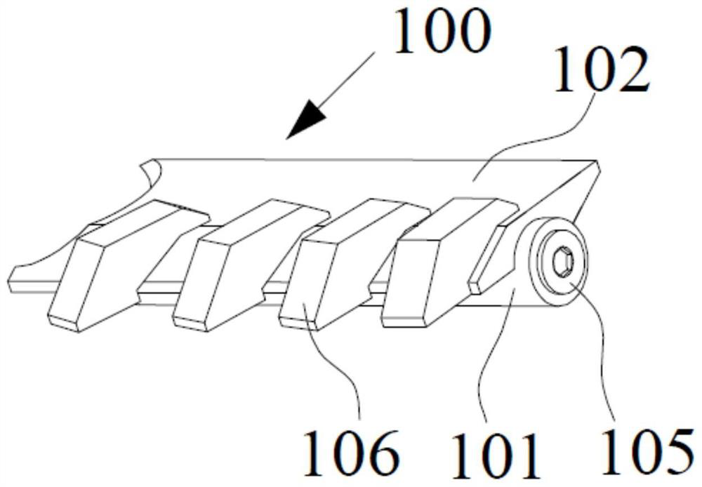
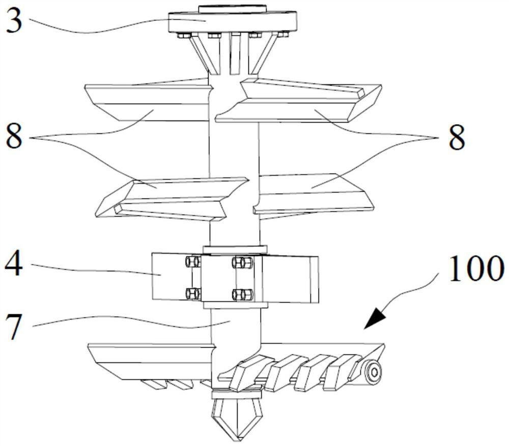
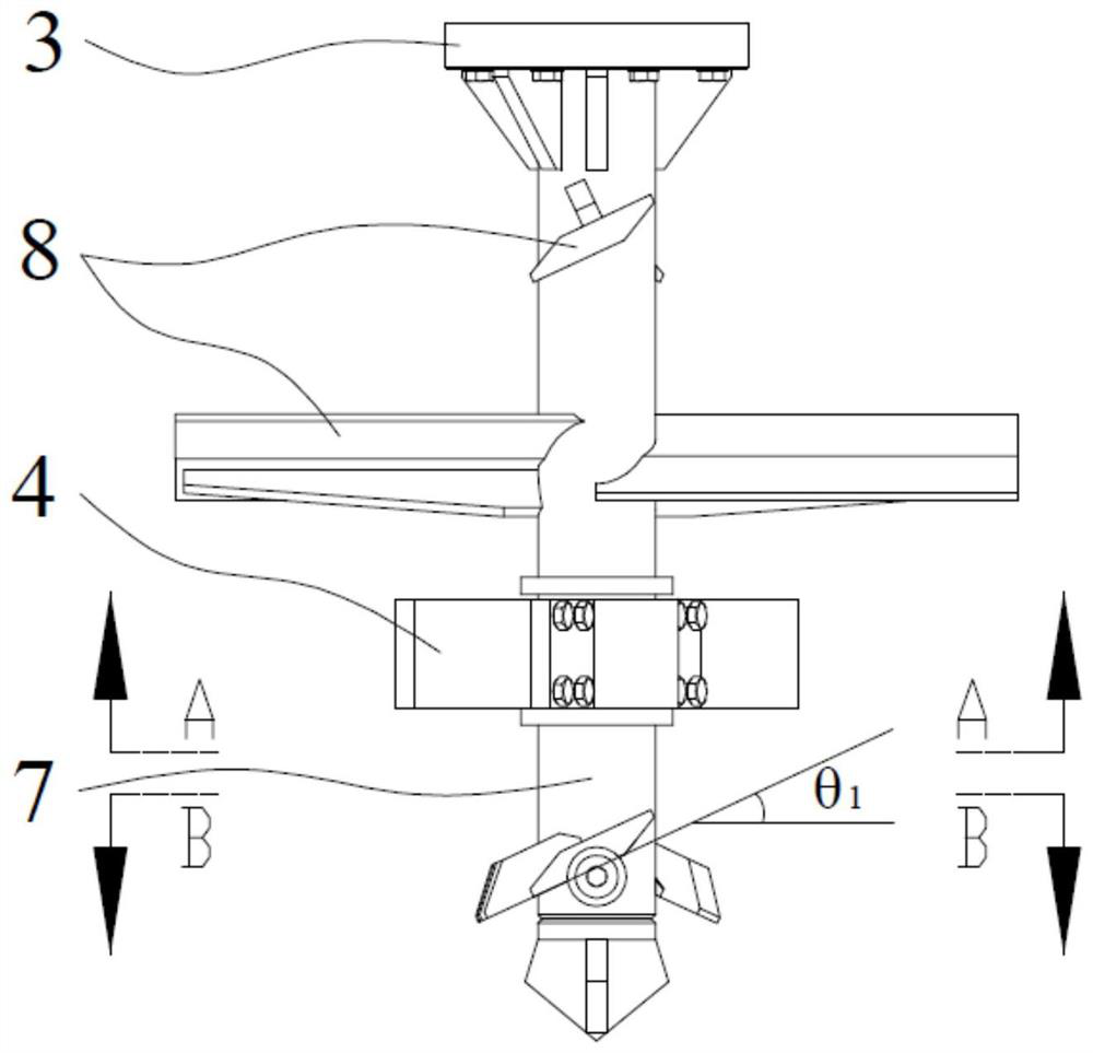
[0028] The present invention will be described in detail below in conjunction with the accompanying drawings: figure 2 Shown is a stirring drill bit using the shotcrete drilling unit 100 of the present invention, the stirring drill bit includes a drill bit joint 3, a drill bit center rod 7, a stirring blade 8, a free blade 4 and a shotcrete excavation unit 100; The shotcrete excavation unit 100 is located in the drill bit The lower end of the center rod 7 and the upper end of the shotcrete excavation unit 100 are provided with a drill bit joint 3, and the rod body of the drill bit center rod 7 is sequentially provided with a stirring blade unit 8 and a free blade 4 from top to bottom, and the stirring blade unit 8 and the free blade are 4 is located above the shotcrete excavation unit 100. The beneficial effects of the invention are as follows: 1. Solve the technical problem that the curing agent cannot be spread evenly during the construction of the traditional stirring pile...


PUM


Abstract

The invention relates to a guniting digging and cutting structure for a large-diameter wet spraying mixing pile construction drilling tool, which comprises a drill bit center rod, a guniting digging and cutting unit is arranged in the radial direction of the drill bit center rod, the guniting digging and cutting unit comprises a guniting channel and a digging and cutting wing plate, and the digging and cutting wing plate is fixed on the outer wall of the drill bit center rod. One end of the slurry spraying channel is communicated with a slurry flowing channel arranged on the drill bit center rod, the slurry spraying channel is located below the digging and cutting wing plate and is parallel to the length direction of the digging and cutting wing plate, and a slurry spraying through seam is formed in the axial direction of the slurry spraying channel; the method has the characteristics of uniformly spreading the curing agent slurry along the radius of the pile body, effectively improving the pile body quality and the construction efficiency of the stirring pile, reducing the dosage of the curing agent and the like, and also has the characteristics of effectively preventing the slurry spraying pipe from being blocked, easily cleaning the blocked pipe and the like.

Description

technical field [0001] The invention belongs to the technical field of underground construction machinery and equipment, and in particular relates to a shotcrete excavation structure used for large-diameter wet shot mixing pile construction drilling tools. Background technique [0002] As a main construction method in the field of foundation treatment engineering technology, deep mixing pile technology has been widely used in the field of engineering construction since the 1960s, including civil engineering, construction engineering, railway engineering, highway engineering, water conservancy engineering, and municipal engineering. and port engineering. The deep mixing pile engineering technology uses a single-shaft or multi-shaft mixing rig to input cement and other curing agents into the ground, and through mixing with soft and hard soil, a series of physical and chemical reactions occur between the curing agent and the soil to generate strength. High, water stability, st...

Claims


Application Information

Patent Timeline
IPC IPC(8): E02D5/46E02D15/04E02D15/02
CPCE02D5/46E02D15/04E02D15/02
Inventor 陈天雄刘钟杨宁晔张楚福
Owner 浙江坤德创新岩土工程有限公司
Why Eureka
Try Eureka