Textile machinery matched wire winding device and use method thereof
A textile machinery and yarn winding technology, which is applied in the field of textile machinery and yarn winding devices, can solve the problems of uneven diameter of spinning, difficulty in spinning without friction, etc., and achieve the effect of small loss of outer surface and improved quality.
- Summary
- Abstract
- Description
- Claims
- Application Information
AI Technical Summary
Problems solved by technology
Method used
Image
Examples
specific Embodiment 1
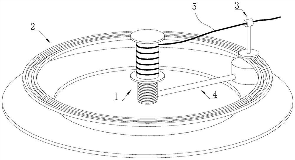
[0037] Specific embodiment 1: please refer to Figure 1-5 A textile machine is matched with a wire winding device, which includes a wire take-up module 1, a wire winding track 2, a wire bundle module 3 and a lifting module 4.
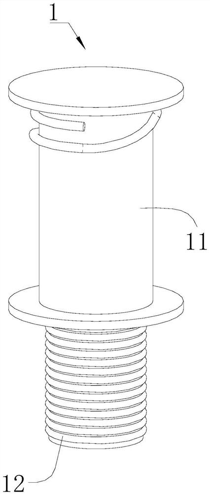
[0038] The wire take-up module 1 includes a wire take-up drum 11 and a flexible airbag 12; the spinning 5 can be wound around the surface of the wire take-up drum 11, the flexible airbag 12 is fixedly connected to the lower end of the wire take-up drum 11, and the bag wall of the flexible airbag 12 is formed only in the vertical direction. The flexible airbag 12 is made of a flexible material with deformability in the direction, and the cavity of the flexible airbag 12 can be expanded or compressed in the vertical direction to drive the wire take-up spool 11 to move in the vertical direction; the lower end of the flexible airbag 12 is fixed on the ground.
[0039] The inner cavity of the flexible airbag 12 is communicated with the inflation cavity throu...
specific Embodiment 2
[0051] Specific embodiment 2: On the basis of specific embodiment 1, please refer to Image 6 The flexible air bag 12 is also connected to the external air pump 6 through a pipeline; the start of the air pump 6 is controlled by the controller, and the air pump 6 can pump the air to the flexible air bag 12 .
[0052] Since the height dimension of the single rise of the flexible airbag 12 is larger than the diameter dimension of the spinning yarn 5, when the spinning yarn 5 is wound from the upper end to the lower end of the take-up drum 11, the gap between the spinning yarns 5 in each turn is too large, and each turn of the spinning yarns 5 is too large. If the number of turns of the layer of spinning 5 is too small, it is difficult to form a tight thread layer, which will cause the next layer of spinning 5 to be embedded in the gap, and it is difficult to collect the spinning 5 in layers. The operation method is as follows:
[0053] A1. Each time the spinning 5 is wound to th...
specific Embodiment 3
[0057] Specific embodiment three: different from specific embodiment one or two, please refer to Figure 7 A kind of textile machinery cooperates with the wire winding device, and the piston rod 42 of the lifting module 4 is replaced with a permanent magnet sealing plate 46;
[0058] The permanent magnet sealing plate 46 is embedded in the air box 41 and is sealed and slidingly connected with the inner wall of the air box 41, and a spring is fixedly arranged between the permanent magnetic sealing plate 46 and the inner top wall of the air box 41; the air box on the lower side of the permanent magnetic sealing plate 46 41 The cavity is an inflatable cavity;
[0059] The driving rod of the beam line module 3 is replaced with an electromagnet 34; the permanent magnet sealing plate 46 is located within the moving range of the electromagnet 34; when the magnetism of the electromagnet 34 and the permanent magnet sealing plate 46 close to each other is the same, the electromagnet 34 ...
PUM
 Abstract
Description
Claims
Application Information
 - Generate Ideas
- Intellectual Property
- Life Sciences
- Materials
- Tech Scout
- Unparalleled Data Quality
- Higher Quality Content
- 60% Fewer Hallucinations
Browse by: Latest US Patents, China's latest patents, Technical Efficacy Thesaurus, Application Domain, Technology Topic, Popular Technical Reports.
© 2025 PatSnap. All rights reserved.Legal|Privacy policy|Modern Slavery Act Transparency Statement|Sitemap|About US| Contact US: help@patsnap.com


