Machine gun rack rotating device for fighter plane and machine gun rack of fighter plane

A technology for rotating devices and fighter jets, which is applied in military equipment configuration, aircraft parts, transportation and packaging, etc. It can solve problems such as increased local friction of rotating parts, difficult rotation of columns, structural deformation and damage of machine gun rack rotating devices, etc., to achieve The effect of increasing the connection strength and correct installation orientation

Active Publication Date: 2022-07-15
北京天创凯睿科技有限公司
View PDF5 Cites 0 Cited by
  • Summary
  • Abstract
  • Description
  • Claims
  • Application Information

AI Technical Summary

Problems solved by technology

[0003] The purpose of the present invention is to provide a machine gun frame rotating device and a fighter machine gun frame for fighters, so as to solve the problem that in the prior art, when a combatant sits on a seat, the rotating connection part of the machine gun frame rotating device will be partially stressed and tilted. As a result, the local friction force of the rotating part increases, the column is not easy to rotate, and even the structural deformation and damage of the machine gun frame rotating device occur.

Method used


Image

  • Machine gun rack rotating device for fighter plane and machine gun rack of fighter plane
  • Machine gun rack rotating device for fighter plane and machine gun rack of fighter plane
  • Machine gun rack rotating device for fighter plane and machine gun rack of fighter plane

Examples


Embodiment 1

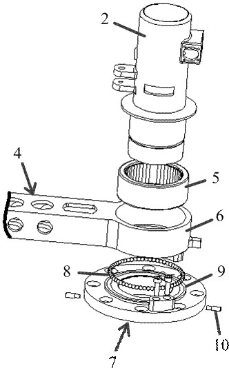
[0065] A machine gun mount turning device for fighter jets is described, such as figure 1 shown, including:

[0066] Machine gun mount base 1, connected to the floor inside the combat helicopter;

[0067] The machine gun support column 2 is arranged on the machine gun mount base 1;

[0068] The seat 3 is rotated, and the rotating seat 3 is rotatably arranged on the machine gun support column 2 through the rotating beam 4; and the rotating beam 4 is rotatably connected to the machine gun support column 2 through the needle roller bearing 5 without an inner ring . like figure 2 As shown, the end of the above-mentioned rotating beam 4 facing the machine gun support column 2 also has an annular connecting sleeve 6; , and the circular needle in the inner cavity of the needle roller bearing without inner ring 5 is connected with the outer peripheral wall of the machine gun support column 2 by rolling friction; the needle roller bearing without inner ring 5 is arranged in the an...

Embodiment 2

[0076] A fighter machine gun mount is documented, such as Figure 5 As shown, it includes: a machine gun mount turning device for a fighter; and a rotating beam 4 .

[0077] The machine gun rack rotating device includes:

[0078] Machine gun mount base 1, connected to the floor inside the combat helicopter;

[0079] The machine gun support column 2 is arranged on the machine gun mount base 1;

[0080] The seat 3 is rotated, and the rotating seat 3 is rotatably arranged on the machine gun support column 2 through the rotating beam 4; and the rotating beam 4 is rotatably connected to the machine gun support column 2 through the needle roller bearing 5 without an inner ring . like figure 2 As shown, the end of the above-mentioned rotating beam 4 facing the machine gun support column 2 also has an annular connecting sleeve 6; , and the circular needle in the inner cavity of the inner ring-free needle roller bearing 5 is connected with the outer peripheral wall of the machine...


PUM


Abstract

The machine gun rack rotating device for the fighter comprises a machine gun rack base connected with a floor in a fighter helicopter, a machine gun rack rotating shaft, a machine gun rack rotating shaft and a machine gun rack rotating shaft, the machine gun supporting column is arranged on the machine gun rack base; the rotating seat is rotationally arranged on the machine gun supporting column through a rotating cross beam; and the rotating cross beam is rotationally connected with the machine gun supporting column through a needle bearing without an inner ring. Through the needle bearing without the inner ring, bending force generated by a rotating seat on the rotating cross beam can be effectively resisted, and the problems that local friction force of a rotating part is increased, a stand column is not prone to rotating, and even a machine gun rack rotating device is structurally deformed and damaged are solved.

Description

technical field [0001] The invention relates to the technical field of combat helicopter rotating seats, in particular to a machine gun mount rotating device for fighter jets and a fighter jet machine gun mount. Background technique [0002] During the flight, a fighter needs to set a machine gun at the position of the cabin door, and the fighters sit on the machine gun seat located in the cabin to attack the target outside the cabin by turning the position of the seat. This requires that the seat used to carry the fighter can be rotated around the column used to fix the machine gun through the beam, so that the fighter can achieve multi-angle free shooting. However, in order to achieve the above effect, the beam with the seat needs to be rotated around the column, because the combined weight of the body weight of the fighter, the weight of the seat and the weight of the beam is relatively heavy, and the column and the seat are respectively arranged on the side of the beam. ...

Claims


Application Information

Patent Timeline
Patent Type & Authority Applications(China)
IPC IPC(8): B64D7/06
CPCB64D7/06
Inventor 王文良崔明宝宋述稳
Owner 北京天创凯睿科技有限公司
Why Eureka
Try Eureka