


Quick Research
Generate reliable direction feasibility study reports for your R&D in just a few steps.

Technical Q&A
Discover and master advanced knowledge NOW. Basics, ideas, possibilities, all at once.

Find Solutions
As an expert in R&D theories, this can generate solutions to your technical problems instantly.

Evaluate Feasibility
Analyze your overall solution with one click, know your potential R&D risks in advance.

Monitor Landscape
Get weekly tech updates, stay abreast of the latest tech innovations and key insights.
Yarn pulp compaction equipment for production of corrosion-resistant glass fiber reinforced plastic grating
A fiberglass and corrosion-resistant technology, which is applied in the field of pulp compaction equipment for corrosion-resistant FRP grating production, can solve the problems of insufficient compaction strength, different content, uneven mortar mixing, etc., to reduce manpower burden, improve low efficiency, The effect of improving efficiency
- Summary
- Abstract
- Description
- Claims
- Application Information
AI Technical Summary
Problems solved by technology
Method used
Image

Examples
Embodiment 1
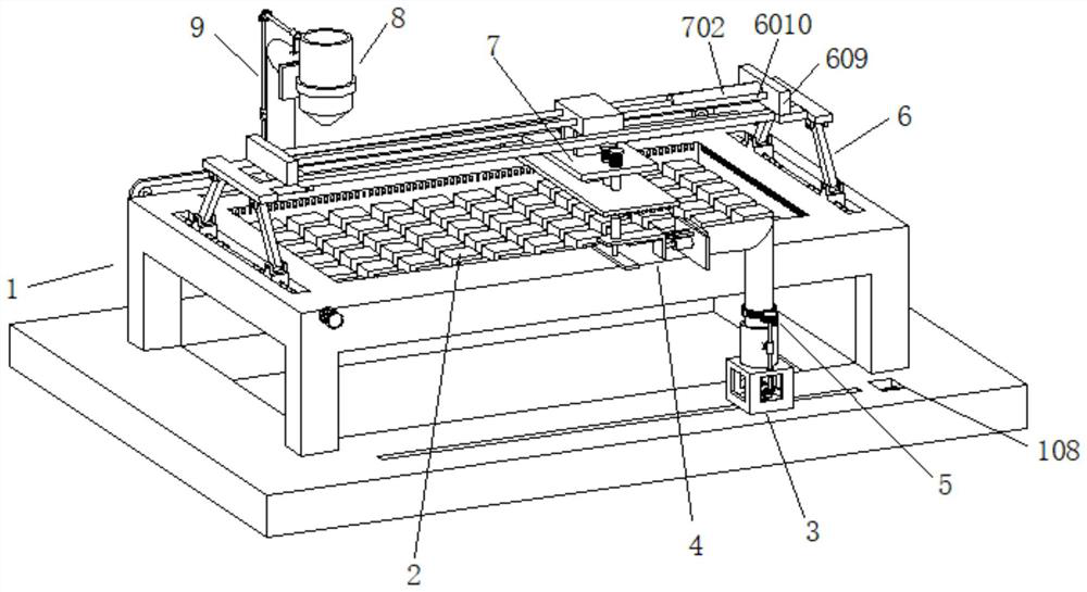
[0054] Embodiment 1 discloses a yarn slurry compaction equipment for the production of corrosion-resistant glass fiber reinforced plastic gratings, refer to the appendix. figure 1 and attached figure 2 , including the base 1 as the load-bearing main body, the front and rear sides of the base 1 are symmetrically provided with a homogenizing device 4 and a feeding device 8, a compaction device 7 is provided above the base 1, and the bottom of the homogenizing device 4 is subject to the moving device 3 and the steering The device 5 is driven, the bottom of the feeding device 8 is provided with a synchronous transmission anti-condensation device 9, and the two ends of the compaction device 7 are provided with a lifting device 6;
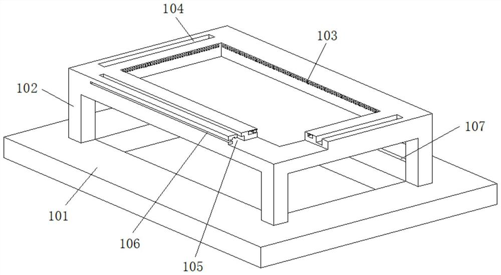
[0055] Reference attached image 3 , the base 1 is composed of a base 101 in an up-down structure and an operating table 102. A module 2 is embedded in the top of the operating table 101, and a liquid return hole 103 is evenly arranged around the modul...
Embodiment 2
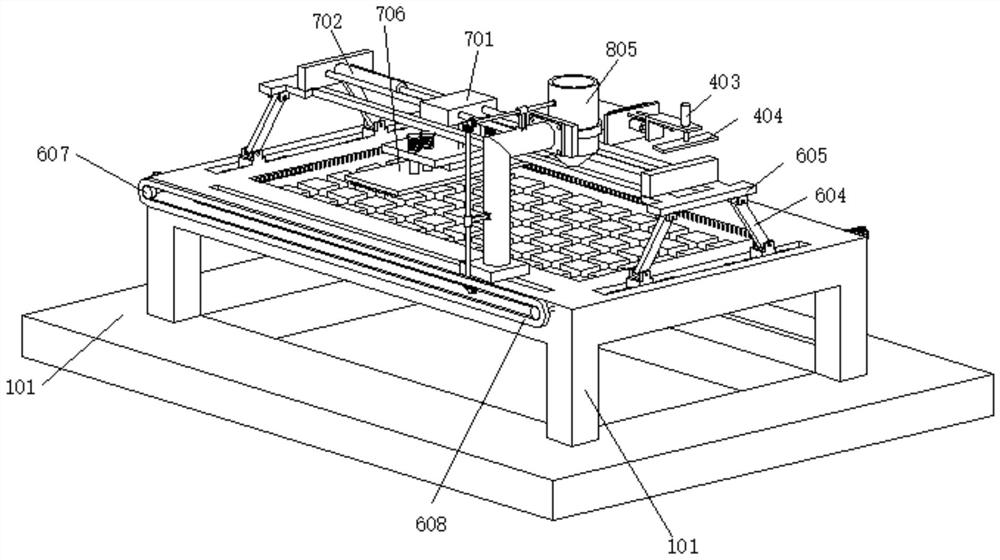
[0064] Example 2 is slightly modified on the basis of Example 1, and the same points will not be repeated. The difference is that a feeding device 8 and an anti-coagulation device 9 for preventing the coagulation of the slurry are added. Refer to the appendix. Figure 9 and attached Figure 10 , the feeding device 8 includes a second screw rod 801 arranged in the chute one 105, the second screw rod 801 is screwed with a third thread seat 802, the top of the third thread seat 802 is provided with a fixed column 803, and the front end of the fixed column 803 A barrel 805 is installed through the positioning ring 804, and a flow valve is installed at the outlet of the barrel 8;
[0065] The anti-condensation device 9 includes a transmission gear 901 installed on one side of the third threaded seat 802 , a rack 902 is fixedly installed under the transmission gear 901 , and the transmission gear 901 rotates synchronously with the third bevel gear 904 through the connecting shaft 90...
PUM
 Abstract
Description
Claims
Application Information
 - R&D Engineer
- R&D Manager
- IP Professional
- Industry Leading Data Capabilities
- Powerful AI technology
- Patent DNA Extraction
Browse by: Latest US Patents, China's latest patents, Technical Efficacy Thesaurus, Application Domain, Technology Topic, Popular Technical Reports.
© 2024 PatSnap. All rights reserved.Legal|Privacy policy|Modern Slavery Act Transparency Statement|Sitemap|About US| Contact US: help@patsnap.com