Preparation device of graphene-based bimetallic nano composite catalyst
A technology of bimetallic nano-composite catalysts, applied to mixers with rotating stirring devices, mixers, transportation and packaging, etc., can solve problems such as difficult handling, influence on preparation, uneven accumulation and mixing of raw materials, etc., and reduce liquid materials The effect of increasing the amount, improving the uniformity, and improving the uniformity of mixing
- Summary
- Abstract
- Description
- Claims
- Application Information
AI Technical Summary
Problems solved by technology
Method used
Image
Examples
Embodiment 1
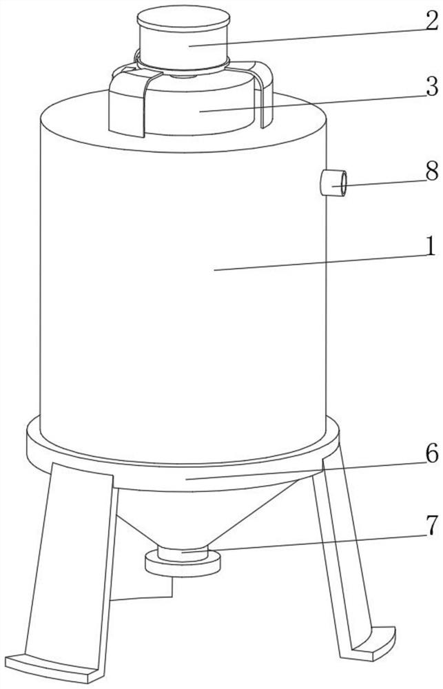
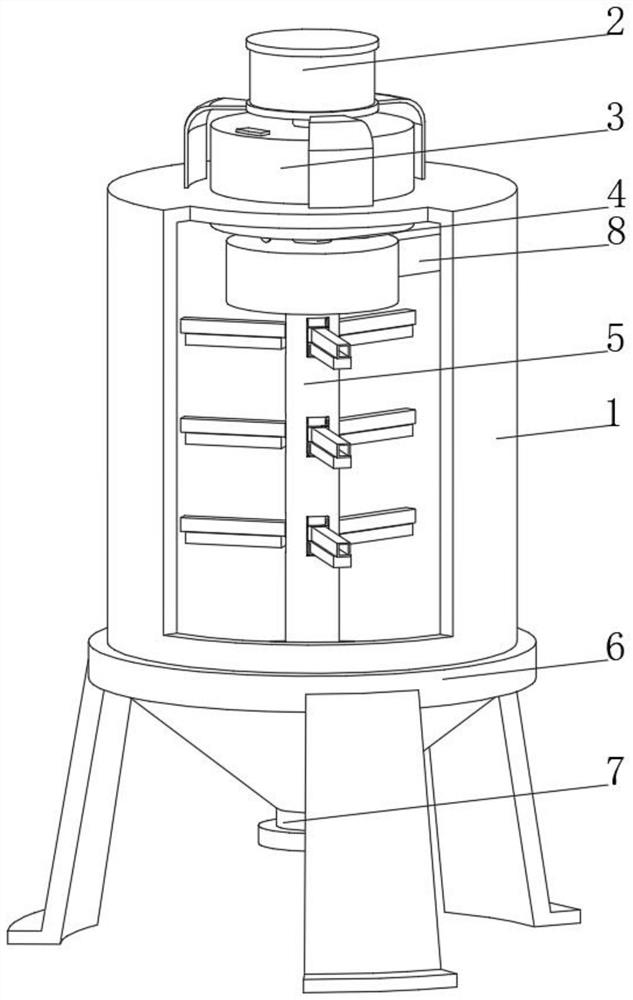
[0040] see Figure 1-Figure 4 , the present invention provides a technical solution: a preparation device for a graphene-based bimetallic nanocomposite catalyst, which specifically includes:
[0041] Preparation cylinder 1, the top of the preparation cylinder 1 is fixedly connected with a drive motor 2 through a bracket, the top of the preparation cylinder 1 is penetrated and fixedly connected with a material storage device 3, and the bottom of the preparation cylinder 1 is communicated with a discharge nozzle 7;
[0042] The stirring shaft 4, the top of the stirring shaft 4 penetrates the storage device 3 and is rotatably connected with the storage device 3, and one end of the stirring shaft 4 penetrates the storage device 3 and is fixedly connected to the drive shaft of the drive motor 2;
[0043] a stirring device 5, the stirring device 5 is arranged inside the preparation drum 1 and is fixedly connected with the bottom of the stirring shaft 4;
[0044] a support frame 6, ...
Embodiment 2
[0055] see Figure 1-Figure 5 , On the basis of the first embodiment, the present invention provides a technical solution: the material storage device 3 includes a material storage box 31, the bottom of the material storage box 31 is fixedly connected with a leakage net 32, and the central position of the leakage net 32 is fixedly connected with a fixed seat 33, the fixed seat The bottom of 33 is rotatably connected with a rotating plate 34 through a bearing, the side of the rotating plate 34 is fixedly connected with an elastic support rod 35, and the end of the elastic support rod 35 away from the rotating disk 34 is fixedly connected with a roller 36, and the bottom of the leakage net 32 is fixedly connected with the position corresponding to the roller 36 There is an inclined sliding table 37, a material spreading device 38 is arranged inside the slip screen 32, the bottom of the storage box 31 runs through the top of the preparation cylinder 1 and extends to the interi...
Embodiment 3
[0057] see Figure 1-Figure 6 , on the basis of Embodiment 1 and Embodiment 2, the present invention provides a technical solution: the material spreading device 38 includes a collar 381, and both sides of the collar 381 are fixedly connected with an arc-shaped push plate 382, and the bottom of the arc-shaped push plate 382 is fixedly connected. A dredging brush 383 is fixedly connected, an extrusion hole 384 is opened on the side of the arc-shaped push plate 382, and an extrusion block 385 is slidably connected to the inner wall of the extrusion hole 384. The collar 381 is sleeved on the rotating shaft 53 and is fixedly connected with the rotating shaft 53 , the top of the extrusion block 385 is fixedly connected with the top of the inner wall of the storage box 31 through the connecting rod, the bottom of the dredging brush 383 extends to the top of the slip screen 32 and is slidably connected to the top of the slip screen 32, and a material spreading device 38 is provide...
PUM
 Abstract
Description
Claims
Application Information
 - R&D
- Intellectual Property
- Life Sciences
- Materials
- Tech Scout
- Unparalleled Data Quality
- Higher Quality Content
- 60% Fewer Hallucinations
Browse by: Latest US Patents, China's latest patents, Technical Efficacy Thesaurus, Application Domain, Technology Topic, Popular Technical Reports.
© 2025 PatSnap. All rights reserved.Legal|Privacy policy|Modern Slavery Act Transparency Statement|Sitemap|About US| Contact US: help@patsnap.com


