Distributed optical fiber sensing system based on delay reservoir calculation and signal identification and positioning method thereof

A distributed optical fiber and sensing system technology, applied in the direction of calculation, calculation model, computer components, etc., can solve the problems of time-consuming, misjudgment of vibration into different types, inaccuracy, etc., and achieve strong learning ability and modeling ability, Less susceptible to noise and simple processing

Pending Publication Date: 2022-07-12
SHANGHAI UNIV
View PDF0 Cites 0 Cited by
  • Summary
  • Abstract
  • Description
  • Claims
  • Application Information

AI Technical Summary

Problems solved by technology

Feature extraction is a time-consuming task and may be inaccurate due to noise interference, so the speed and accuracy of recognition need to be improved
More importantly, most of the research on signal recognition does not consider the location of the vibration, and the same type of vibration at different locations may be misjudged as different types.

Method used


Image

  • Distributed optical fiber sensing system based on delay reservoir calculation and signal identification and positioning method thereof
  • Distributed optical fiber sensing system based on delay reservoir calculation and signal identification and positioning method thereof
  • Distributed optical fiber sensing system based on delay reservoir calculation and signal identification and positioning method thereof

Examples


Embodiment 1

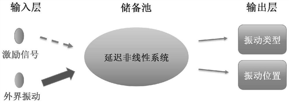
[0030] In this example, see figure 1 , a distributed optical fiber sensing system based on reserve pool computing, which consists of an input layer, a reserve pool and an output layer. The input layer has two nodes, one is inputting the excitation signal of the reserve pool, and the other is inputting the external vibration signal; the reserve pool is composed of a delay nonlinear system, and the delay fiber is the sensing fiber; the output layer has two nodes. nodes, one outputs the vibration type and the other outputs the vibration location.

[0031] In this embodiment, the optical fiber delay nonlinear system is used as both a reserve pool and a sensor, and the response of the reserve pool calculation is used to detect the external vibration signal; through the idea of ​​machine learning, that is, the training and testing of the reserve pool calculation, the external vibration Type identification and location determination of signals. There is no need to build an accurate...

Embodiment 2

[0033] This embodiment is basically the same as the first embodiment, and the special features are:

[0034] In this embodiment, the node for inputting the excitation signal of the reserve pool in the input layer is not necessary, that is, there is or does not exist as required.

[0035] In this embodiment, the delay nonlinear system is an all-optical delay form or a photoelectric delay form, and the specific structure requires that it not only has the properties of a storage pool, but also has different responses to different types of external vibrations at different locations.

[0036] Compared with the reserve pool calculation implemented by software, the virtual node state acquisition speed of this embodiment is fast, and therefore, the process of signal identification and positioning is also fast.

Embodiment 3

[0038] This embodiment is basically the same as the above-mentioned embodiment, and the special features are:

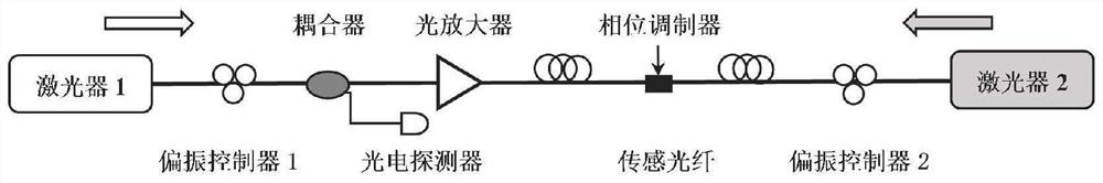
[0039] In this example, see figure 2 , using the delayed mutual injection semiconductor laser system to form the storage pool and the distributed fiber optic sensor. Both Laser 1 and Laser 2 are semiconductor lasers without built-in isolators. Two polarization controllers are used to adjust the polarization state of the light injected into the two lasers. A section of fiber connecting the two lasers is used as the sensing fiber, and a phase modulator is inserted into the sensing fiber to simulate the effect of external vibration on the sensing fiber, that is, as the only input node to input external vibration signals. In order to make up for the loss of light on the mutual injection channel and ensure that the two lasers have sufficient mutual injection strength, an optical amplifier is placed in the mutual injection channel. Part of the optical signal is output ...


PUM


Abstract

The invention discloses a distributed optical fiber sensing system based on delay reservoir calculation and a signal identification and positioning method thereof. The system is composed of an input layer, a storage pool and an output layer. The input layer is provided with two nodes, one node is used for inputting a non-necessary reservoir excitation signal, and the other node is used for inputting an external vibration signal; the storage pool is composed of a delay nonlinear system, and a delay optical fiber of the delay nonlinear system is a sensing optical fiber; the output layer is provided with two nodes, one node outputs a vibration type, and the other node outputs a vibration position. The signal identification and positioning method comprises the following steps of: before a system is started, carrying out network training, and determining an output connection right according to a virtual node state of target output and training signals; and after the system is started, the output connection weight and the virtual node state of the to-be-detected vibration signal are utilized to obtain the output calculated by the reserve pool, namely the type and the position of the vibration signal. According to the invention, the light reserve pool is utilized to calculate strong learning ability, modeling ability and rapid processing ability, and accurate and real-time identification and positioning of external vibration are realized.

Description

technical field [0001] The invention relates to a distributed optical fiber sensing system and a signal identification and positioning method thereof, in particular to a distributed optical fiber sensing system based on delay reserve pool calculation and a signal identification and positioning method thereof, belonging to the field of optical fiber sensing. Background technique [0002] Distributed optical fiber sensing systems use optical fibers as sensitive components and transmission media to continuously monitor external vibration signals over long distances, and have developed rapidly in the fields of pipeline safety detection and perimeter defense. At present, the distributed optical fiber vibration sensing technology generally has the problems of high false alarm rate, low positioning accuracy and slow processing speed. [0003] In recent years, the application of machine learning in distributed optical fiber vibration sensing has gradually become a research hotspot. ...

Claims


Application Information

Patent Timeline
Patent Type & Authority Applications(China)
IPC IPC(8): G01H9/00G06K9/00G06N3/08G06N20/00
CPCG01H9/004G06N3/08G06N20/00G06F2218/12
Inventor 方捻王帅王陆唐王春华
Owner SHANGHAI UNIV
Why Eureka
Try Eureka