Tool for detecting coating condition of heat-conducting silicone grease

A technology for detecting tooling and thermal grease, applied in color measurement devices, mechanical thickness measurement, etc., can solve the problems of consistent coating thickness of thermal grease, observing and judging thermal grease, the influence of coating conditions, etc.

Pending Publication Date: 2022-07-12
YANTAI TAIXIN ELECTRONICS TECH CO LTD
View PDF13 Cites 0 Cited by
  • Summary
  • Abstract
  • Description
  • Claims
  • Application Information

AI Technical Summary

Problems solved by technology

[0002] The IGBT module is a composite fully-controlled voltage-driven power semiconductor device composed of a bipolar transistor and an insulated gate field effect transistor. The copper base plate is an important substrate on the IGBT module. When preparing the copper base plate, part of the copper base plate is in the There is a certain degree of curvature after completion, and the degree of curvature will affect the coating of thermally conductive silicone grease on the copper base plate. The copper base plate corresponding to the specified curvature value is directly coated with a single layer of thermally conductive silicone grease. The entire surface coating operation will cause the coating thickness of the thermal conductive silicone grease to be consistent, which is not conducive to the operator to directly observe and judge the relationship between the coating of the thermal conductive silicone grease and the bending of the bottom plate with the naked eye. It is inconvenient to produce statistics and provide more accurate detection standards for the bending degree of copper base plate materials in the later stage

Method used


Image

  • Tool for detecting coating condition of heat-conducting silicone grease
  • Tool for detecting coating condition of heat-conducting silicone grease
  • Tool for detecting coating condition of heat-conducting silicone grease

Examples


Embodiment 1

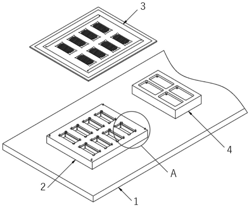
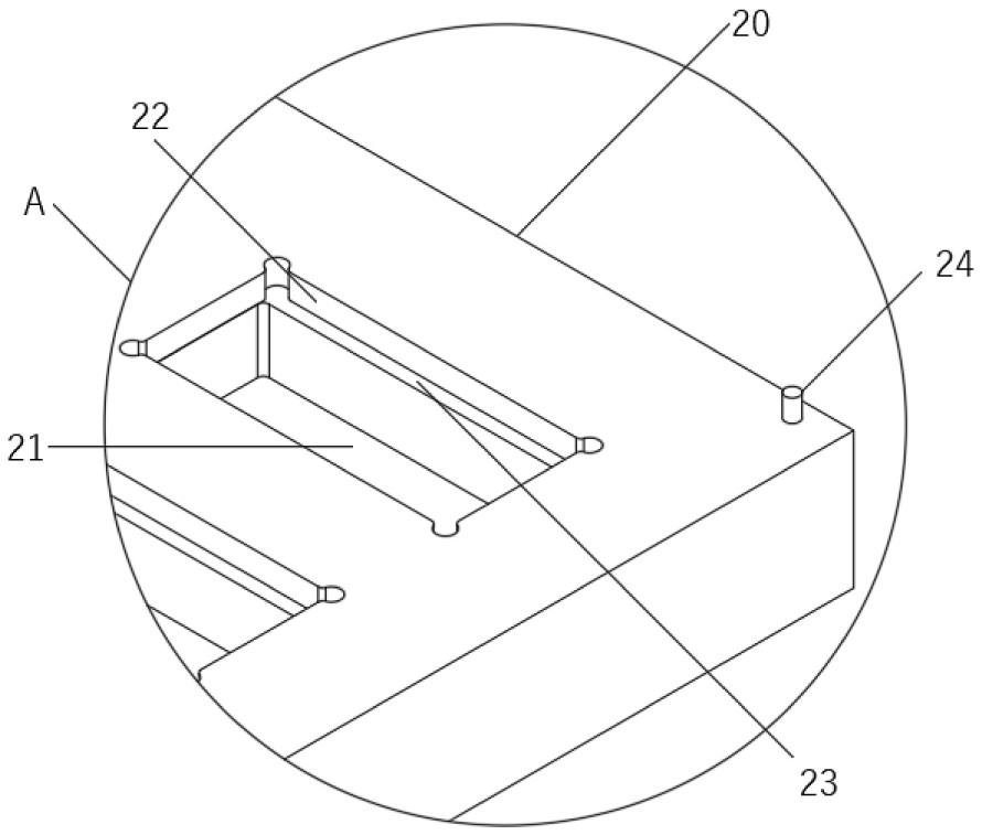
[0038] see Figure 1-Figure 4 , this embodiment provides a technical solution: a thermal conductive silicone grease coating condition detection tool, including a placement mold 2 arranged on the work table 1, the placement mold 2 includes a rectangular plate 20, and the rectangular plate 20 is provided with a plurality of The placement grooves 21 arranged in a matrix, a groove 22 is provided on the groove wall at the top position of the placement groove 21, and two symmetrical step surfaces 23 are arranged between the placement groove 21 and the groove 22. , it is convenient to place the module on the stepped surface 23, so that the bottom of the module is suspended, preventing the terminal at the bottom of the module from contacting the desktop or being squeezed to cause the module to fail;

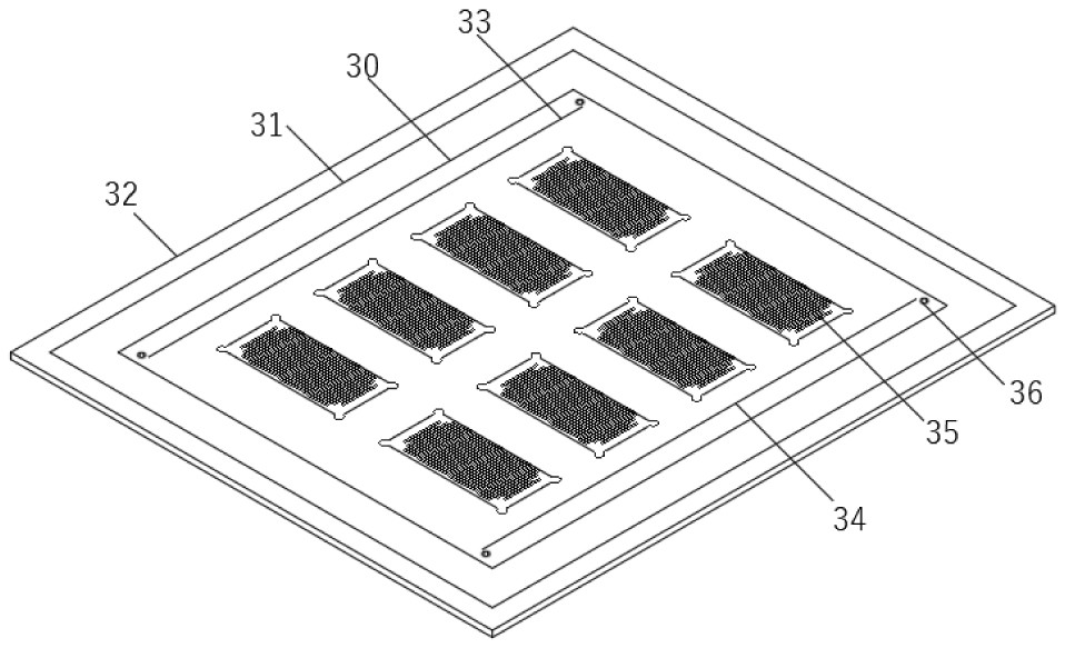
[0039] Specifically, a steel mesh 3 is provided above the placement mold 2, and the steel mesh 3 includes a center plate 30. A plurality of coating holes 35 communicated with the outside a...

Embodiment 2

[0047] see Figure 5-Figure 6 , the difference between this embodiment and Embodiment 1 is that a sleeve box 50 is fixedly installed on the bottom surface of the outer plate 31 , the sleeve box 50 is sleeved on the rectangular plate 20 , and the size of the rectangular plate 20 is just suitable for the size of the sleeve box 50 After the sleeve box 50 is placed on the rectangular plate 20, the outer plate 31 can be further positioned, so that the outer plate 31 can be correctly placed on the upper surface of the rectangular plate 20 more smoothly, which is further beneficial to ensure the central plate 30. The positional mismatch with the rectangular plate 20 is unlikely to occur.

[0048] In this embodiment, an annular groove 5 is provided on the work surface 1, and a pressing device 6 is arranged at the position of the annular groove 5. The pressing device 6 includes a bearing 60 whose outer ring is fixedly installed on the groove wall of the annular groove 5. A support col...

Embodiment 3

[0053] see Figure 7-Figure 8 The difference between this embodiment and Embodiment 1 is that an ejector device 7 is provided at the bottom of the work table 1, and the ejector device 7 includes a hydraulic cylinder 70 arranged under the work table 1, and a bottom plate is provided on the telescopic shaft of the hydraulic cylinder 70 72. A plurality of lifting plates 73 arranged in a matrix are fixedly installed on the top surface of the bottom plate 72. The lifting plates 73 are located in the placing groove 21 and are slidably connected with the placing groove 21, so as to facilitate the use of the hydraulic cylinder 70 to work and drive the The lifting plate 73 is lifted upwards to push out the modules in the placement slot 21 to the outside, so that the module can be taken out from the placement slot 21 more smoothly.

[0054] In this embodiment, a steel plate 71 is fixedly installed at the end of the telescopic shaft of the hydraulic cylinder 70 , and the bottom plate 72 ...


PUM


Abstract

The invention relates to the technical field of IGBT (Insulated Gate Bipolar Translator) module coating detection tools, in particular to a heat-conducting silicone grease coating condition detection tool, which comprises a placement mold arranged on a working table, the placement mold comprises a rectangular plate, a plurality of placement grooves arranged in a matrix manner are formed in the rectangular plate, grooves are formed in the groove walls of the tops of the placement grooves, and the grooves are communicated with the placement mold. A steel mesh is arranged above the placing die, a mounting die is further arranged on the working table, the mounting die comprises a die plate arranged on the working table, a plurality of detection grooves communicated with the outside are formed in the die plate, four screw holes arranged in a matrix mode are formed in the bottom wall of each detection groove, an annular groove is formed in the working table, and the mounting die is arranged in the annular groove. A pressing device is arranged at the position of the annular groove, an ejection device is arranged at the bottom of the working table top, and the ejection device comprises a hydraulic cylinder arranged below the working table top. The coating condition can be observed by naked eyes, operation and use are convenient, and convenience is brought to a user.

Description

technical field [0001] The invention relates to the technical field of IGBT module coating coating detection tools, in particular to a thermal conductive silicone grease coating condition detection tool. Background technique [0002] The IGBT module is a composite fully controlled voltage-driven power semiconductor device composed of bipolar transistors and insulated gate field effect transistors. The copper base plate is an important substrate on the IGBT module. There is a certain degree of curvature after completion, and the degree of curvature will affect the coating of thermal conductive silicone grease on the copper base plate. Now, when the copper base plate corresponding to the specified curvature value is coated with a single layer of thermal conductive grease, it is directly Carrying out the whole surface coating operation will cause the coating thickness of the thermal grease to be consistent, which is not conducive to the operator to directly observe and judge ...

Claims


Application Information

Patent Timeline
IPC IPC(8): G01B5/06G01J3/46
CPCG01B5/066G01J3/46
Inventor 姜维宾和西栋周仁政
Owner YANTAI TAIXIN ELECTRONICS TECH CO LTD
Why Eureka
Try Eureka