Grate tooth sealing structure

A technology of grate tooth and tooth cavity, which is applied in the field of grate tooth sealing structure, to achieve the effect of increasing energy dissipation, reducing fluid leakage and avoiding large vibration

Pending Publication Date: 2022-07-12
AECC SHENYANG ENGINE RES INST
View PDF0 Cites 0 Cited by
  • Summary
  • Abstract
  • Description
  • Claims
  • Application Information

AI Technical Summary

Problems solved by technology

[0007] However, the sealing performance of various existing sealing structures depends entirely on structural parameters, including ...

Method used


Image

  • Grate tooth sealing structure
  • Grate tooth sealing structure
  • Grate tooth sealing structure

Examples


Embodiment Construction

[0030] In order to make the implementation purpose, technical solutions and advantages of the present application clearer, the technical solutions in the embodiments of the present application will be described in more detail below with reference to the accompanying drawings in the embodiments of the present application.

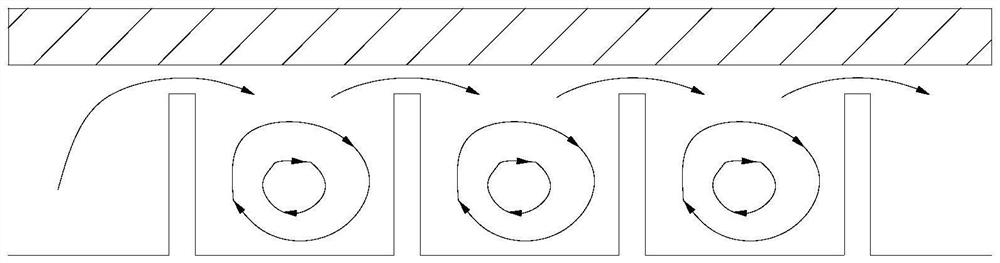
[0031] Under normal circumstances, the gap control of the grate seal structure is difficult. The reason is that vibration, deformation, wear, yaw and other reasons make it difficult to maintain the grate seal gap at a small value. The gap between the receivers will not be too small, and when the gap is large, it will cause a large amount of cold air leakage.

[0032] In order to overcome the above problems, the present application proposes a grate sealing structure that can reduce gas leakage in the sealing flow path and no longer pursue a small sealing gap.

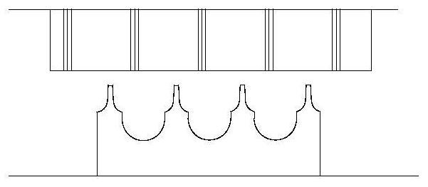
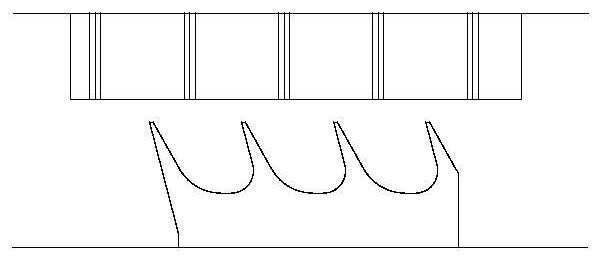
[0033] like image 3 and Figure 4 As shown, the grate sealing structure provided by the present ...


PUM


Abstract

The invention provides a labyrinth sealing structure which comprises a lining and a rotor, the rotor is provided with at least two labyrinth teeth, so that a tooth cavity is formed between the two labyrinth teeth, at least one set of impact holes are formed in the middle position, matched with the tooth cavity, of the lining, and the impact holes are formed in the middle position, matched with the tooth cavity, of the lining. And the turbulent flow introduced from the impact hole forms an air curtain in the tooth cavity, and the air curtain can prevent leakage of gas in the sealed air guide flow path and destroy vortex systems in the tooth cavity at the same time, so that a larger vortex system is impacted into two smaller vortex systems. According to the labyrinth sealing structure provided by the invention, for an original labyrinth sealing air path, turbulent airflow is increased to form an air screen, when a labyrinth gap is greatly changed, a strong blocking effect is formed on the original sealing air path, leakage increase caused by gap increase is relieved to a certain extent, energy dissipation in a tooth cavity is increased, and the sealing effect of the labyrinth sealing structure is improved. Therefore, fluid leakage of an original gas circuit is reduced.

Description

technical field [0001] The present application belongs to the technical field of aero-engines, and particularly relates to a grate sealing structure. Background technique [0002] In the structure of aero-engines, the grate seal is widely used between relatively rotating components to isolate high pressure due to its simple structure, low cost, easy maintenance, high reliability at high temperature and high speed, and good rotor dynamics. areas and low pressure areas. [0003] The function of the grate seal structure is mainly reflected in two aspects: one is to control the air flow, to achieve minimum leakage or to meet quantitative sealing requirements, for example, the compressor or turbine interstage seal wants the flow to be as small as possible to reduce leakage loss, Excessive high temperature and high pressure gas leaking into the bearing cavity will cause the temperature and pressure of the bearing cavity to rise, causing damage to the bearing and lubricating oil, ...

Claims


Application Information

Patent Timeline
IPC IPC(8): F02C7/28F01D11/04
CPCF02C7/28F01D11/04Y02T10/12
Inventor 赵家军王家友范宇赵耘墨
Owner AECC SHENYANG ENGINE RES INST
Why Eureka
Try Eureka