
Tunnel advance horizontal jet grouting pile built-in steel pipe positioning device

A technology of horizontal rotary jetting pile and positioning device, which is applied in tunnels, tunnel linings, shaft equipment, etc., can solve problems such as position deviation, and achieve the effects of fast efficiency, simple installation and improved pile strength.

Pending Publication Date: 2022-07-12
甘肃省交通规划勘察设计院股份有限公司
View PDF0 Cites 0 Cited by
  • Summary
  • Abstract
  • Description
  • Claims
  • Application Information

AI Technical Summary

Problems solved by technology

[0005] The purpose of the present invention is to solve the position deviation problem in the construction process of steel pipes in the prior art, and provide a kind of reinforcement effect of the horizontal jet grouting pile, which can fully exert the reinforcement effect of the horizontal jet grouting pile and ensure that the steel pipe is located in the center of the pile body. Positioning means

Method used


Image

  • Tunnel advance horizontal jet grouting pile built-in steel pipe positioning device
  • Tunnel advance horizontal jet grouting pile built-in steel pipe positioning device
  • Tunnel advance horizontal jet grouting pile built-in steel pipe positioning device

Examples


Embodiment Construction

[0034] The present invention will be further described below with reference to the accompanying drawings and specific embodiments.

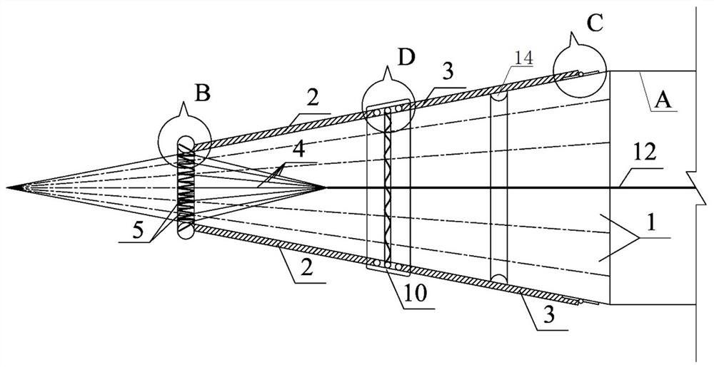
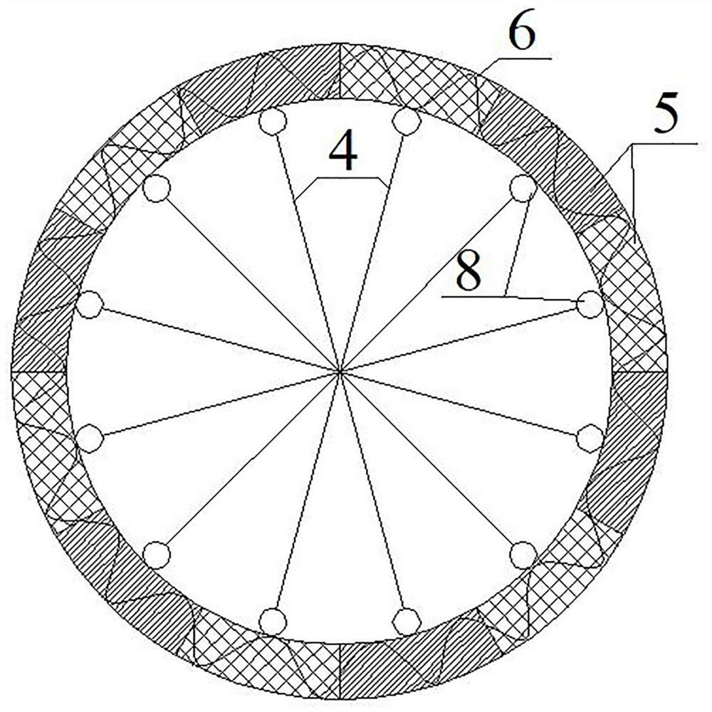
[0035] like Figure 1-11 As shown in the figure, a built-in steel pipe positioning device for an advanced horizontal rotary jetting pile in a tunnel includes a plurality of front support rods 2 arranged at intervals in a small section of the cone portion of the steel pipe and a plurality of rear support rods arranged at intervals in a large section of the cone section of the steel pipe. 3. A support body D is arranged between the front support rod 2 and the rear support rod, and the support body D includes a support plate 10, and hinges 9 are welded on both sides of the bottom of each support plate 10. The support rod 2 is welded, one end of the other hinge 9 is welded with the rear support rod 3, the bottom of each support plate 10 is welded with a sleeve 7, the sleeve 7 is connected by a soft spring 11, and the two ends of the soft spring 11 ar...


PUM

PropertyMeasurementUnit
Lengthaaaaaaaaaa
Diameteraaaaaaaaaa

Abstract

The invention belongs to the technical field of tunnel reinforcement safety steel pipe positioning, and discloses a tunnel advanced horizontal jet grouting pile built-in steel pipe positioning device to solve the problem of position deviation in the steel pipe construction process in the prior art. The steel pipe positioning device comprises a plurality of front supporting rods arranged on the small section of the pointed cone portion of the steel pipe at intervals and a plurality of rear supporting rods arranged on the large section of the pointed cone portion of the steel pipe at intervals, supporting bodies are hinged between the front supporting rods and the rear supporting rods, and the ends, away from the supporting bodies, of the rear supporting rods are hinged to the side wall of the pointed cone portion of the steel pipe. An elastic movable clamping ring is arranged at the end, away from the supporting body, of the front supporting rod and provided with a tension mechanism which can enable the elastic movable clamping ring to be clamped in the large-section groove of the pointed cone part of the steel pipe. Through the umbrella bundle telescopic structure, the position of the steel pipe is positioned and restrained, and the purposes of precise construction and improvement of the pile body strength are achieved. In addition, the device can be integrally manufactured in a factory to form a new steel pipe positioning fixing head, and is simple and convenient to weld and install on site, low in cost and high in efficiency.

Description

technical field [0001] The invention relates to the technical field of tunnel reinforcement steel pipe positioning, in particular to a built-in steel pipe positioning device for a tunnel advanced horizontal rotary jetting pile. Background technique [0002] In recent years, during the construction of highway tunnels, some sections pass through loose sandstone, sand-like structure, thick-layered structure, weak muddy cementation (contact cementation), poor diagenesis, easy to soften and disintegrate when exposed to water, and natural compressive strength. 1.33~4.13MPa, it is a very soft rock. When the tunnel passes through the stratum, with the excavation of the tunnel, the surrounding rock is in a state of being in the air, and the stress conditions are changed. The stress release of the original rock and the disturbance effect of the excavation on the surrounding rock, the stress release is fast, the initial deformation rate, deformation Due to the large amount of rock, th...

Claims


Application Information

Patent Timeline
IPC IPC(8): E21D11/10E21D11/00
CPCE21D11/003E21D11/107
Inventor 杨治军刘泾堂张耀庭胡金鑫邱成虎包正龙王文卓薄士威朱强斌郑继祖
Owner 甘肃省交通规划勘察设计院股份有限公司
Learn More