Air-locking discharging device for centrifugal spray dryer
A technology of centrifugal spray drying and unloading device, applied in the directions of loading/unloading, transportation and packaging, cleaning of hollow objects, etc., can solve the problems of general air locking effect, inconvenient cleaning, etc., to achieve rich device functions, convenient cleaning and maintenance, The effect of reducing the difficulty of cleaning and maintenance
- Summary
- Abstract
- Description
- Claims
- Application Information
AI Technical Summary
Problems solved by technology
Method used
Image
Examples
Embodiment 1
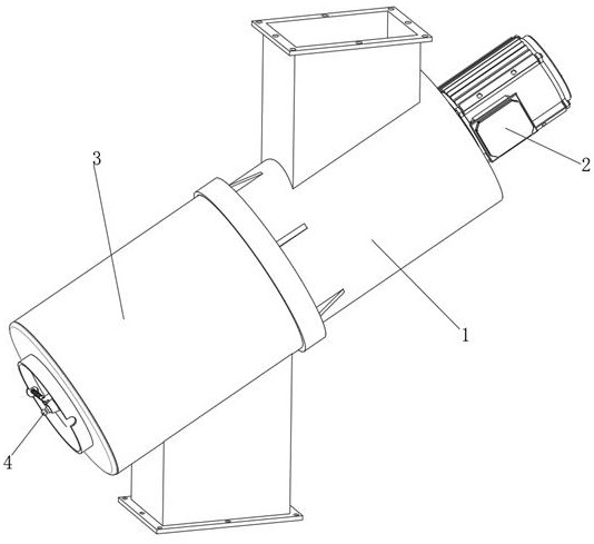
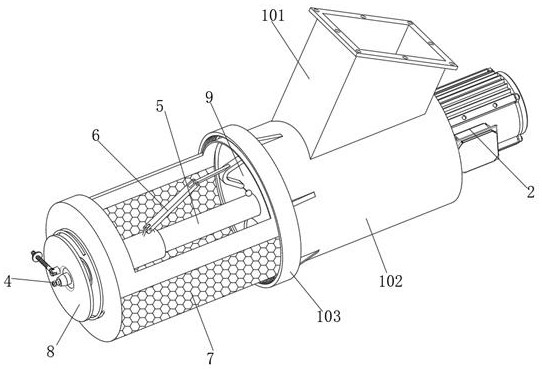
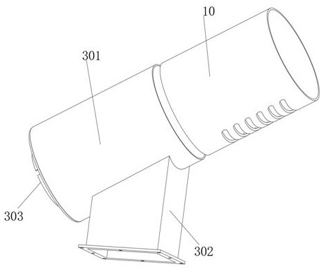
[0042] Example 1, refer to figure 1 , figure 2 , image 3 , Figure 4 , Figure 5 , Image 6 , Figure 7 , Figure 8 , Figure 9 and Figure 10 , an air-locking and unloading device for centrifugal spray dryers, comprising a feeding assembly 1 and a discharging assembly 3, the feeding assembly 1 and the discharging assembly 3 are connected by bolts, and the feeding assembly 1 A separating plate 9 is provided between the feeding assembly 3 and the feeding assembly 3, a feeding assembly 5 is rotated in the feeding assembly 1, and a motor 2 for driving the feeding assembly 5 to rotate is provided on the feeding assembly 1. The feeding component 5 includes a metal shaft 501, and the outer peripheral surface of the metal shaft 501 is circumferentially distributed with a plurality of partitions 502 near the inner side of the feeding component 1. The end of the metal shaft 501 close to the discharging component 3 is a tubular structure. The outer peripheral surface of 501 i...
Embodiment 2
[0046] Example 2, refer to figure 1 , figure 2 , image 3 , Figure 4 , Figure 5 , Image 6 , Figure 7 , Figure 8 , Figure 9 and Figure 10 , an air-locking and unloading device for centrifugal spray dryers, comprising a feeding assembly 1 and a discharging assembly 3, the feeding assembly 1 and the discharging assembly 3 are connected by bolts, and the feeding assembly 1 A separating plate 9 is provided between the feeding assembly 3 and the feeding assembly 3, a feeding assembly 5 is rotated in the feeding assembly 1, and a motor 2 for driving the feeding assembly 5 to rotate is provided on the feeding assembly 1. The feeding assembly 5 includes a metal shaft 501, and the outer peripheral surface of the metal shaft 501 is circumferentially distributed with a plurality of partitions 502 near the inner side of the feeding assembly 1. The metal shaft 501 has a tubular structure at one end near the discharging assembly 3. The outer peripheral surface of 501 is prov...
Embodiment 3
[0051] Example 3, refer to figure 1 , figure 2 , image 3 , Figure 4 , Figure 5 , Image 6 , Figure 7 , Figure 8 , Figure 9 and Figure 10 , an air-locking and unloading device for centrifugal spray dryers, comprising a feeding assembly 1 and a discharging assembly 3, the feeding assembly 1 and the discharging assembly 3 are connected by bolts, and the feeding assembly 1 A separating plate 9 is provided between the feeding assembly 3 and the feeding assembly 3, a feeding assembly 5 is rotated in the feeding assembly 1, and a motor 2 for driving the feeding assembly 5 to rotate is provided on the feeding assembly 1. The feeding assembly 5 includes a metal shaft 501, and the outer peripheral surface of the metal shaft 501 is circumferentially distributed with a plurality of partitions 502 near the inner side of the feeding assembly 1. The metal shaft 501 has a tubular structure at one end near the discharging assembly 3. The outer peripheral surface of 501 is prov...
PUM
 Abstract
Description
Claims
Application Information
 - Generate Ideas
- Intellectual Property
- Life Sciences
- Materials
- Tech Scout
- Unparalleled Data Quality
- Higher Quality Content
- 60% Fewer Hallucinations
Browse by: Latest US Patents, China's latest patents, Technical Efficacy Thesaurus, Application Domain, Technology Topic, Popular Technical Reports.
© 2025 PatSnap. All rights reserved.Legal|Privacy policy|Modern Slavery Act Transparency Statement|Sitemap|About US| Contact US: help@patsnap.com


