Wafer separator and carton production line

A technology of slicing machine and swinging machine, which is applied in papermaking, paper/cardboard containers, final product manufacturing, etc., can solve the problems of low production efficiency and high labor intensity, and achieve the effect of improving production efficiency and reducing labor intensity

Pending Publication Date: 2022-07-12
GUANGDONG DONGFANG PRECISION SCI & TECH CO LTD
View PDF0 Cites 0 Cited by
  • Summary
  • Abstract
  • Description
  • Claims
  • Application Information

AI Technical Summary

Problems solved by technology

[0004] In view of the shortcomings of the above-mentioned prior art, the purpose of the present invention is to provide a slicing machine and a carton production line, which aims to solve the problems of high labor intensity and low production efficiency caused by the need for manual slicing of existing cardboard

Method used


Image

  • Wafer separator and carton production line
  • Wafer separator and carton production line
  • Wafer separator and carton production line

Examples


Embodiment Construction

[0024] The present invention provides a slicing machine and a carton production line. In order to make the purpose, technical solutions and effects of the present invention clearer and clearer, the present invention will be further described in detail below with reference to the accompanying drawings and examples. It should be understood that the specific embodiments described herein are only used to explain the present invention, but not to limit the protection scope of the present invention.

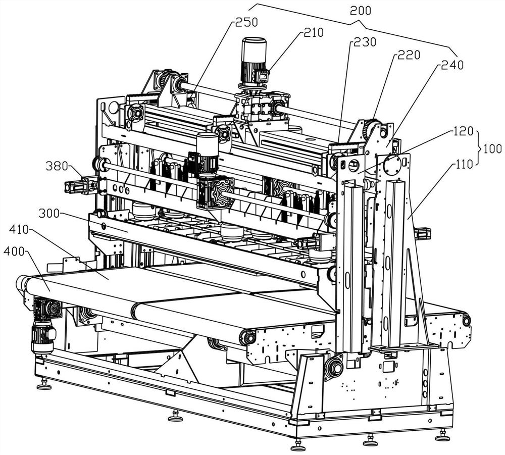
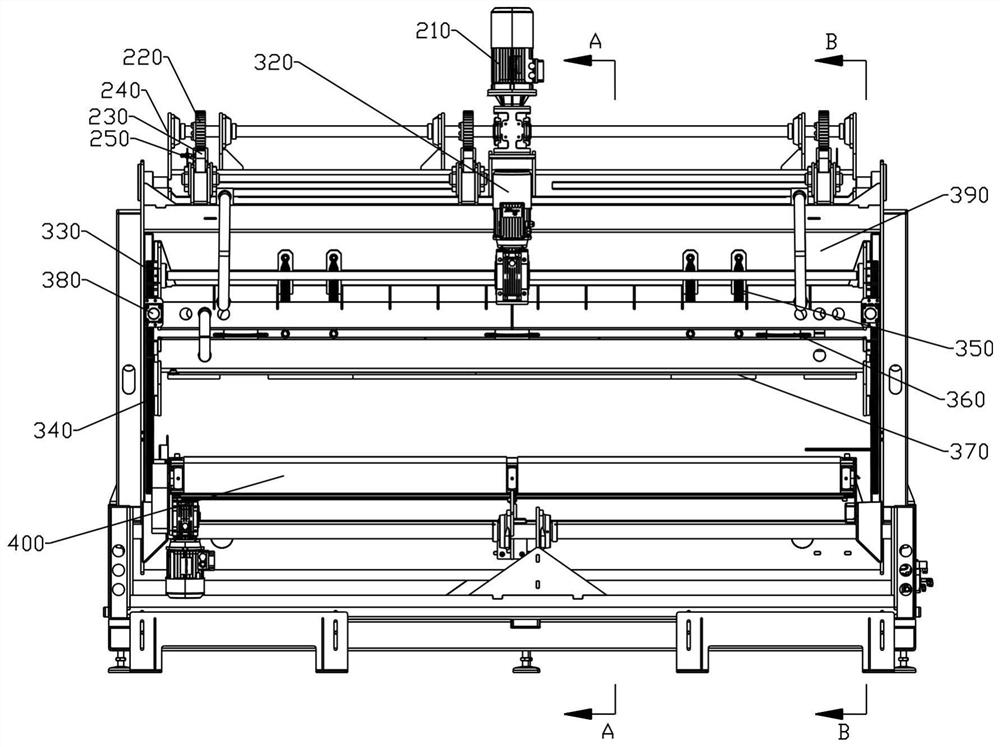
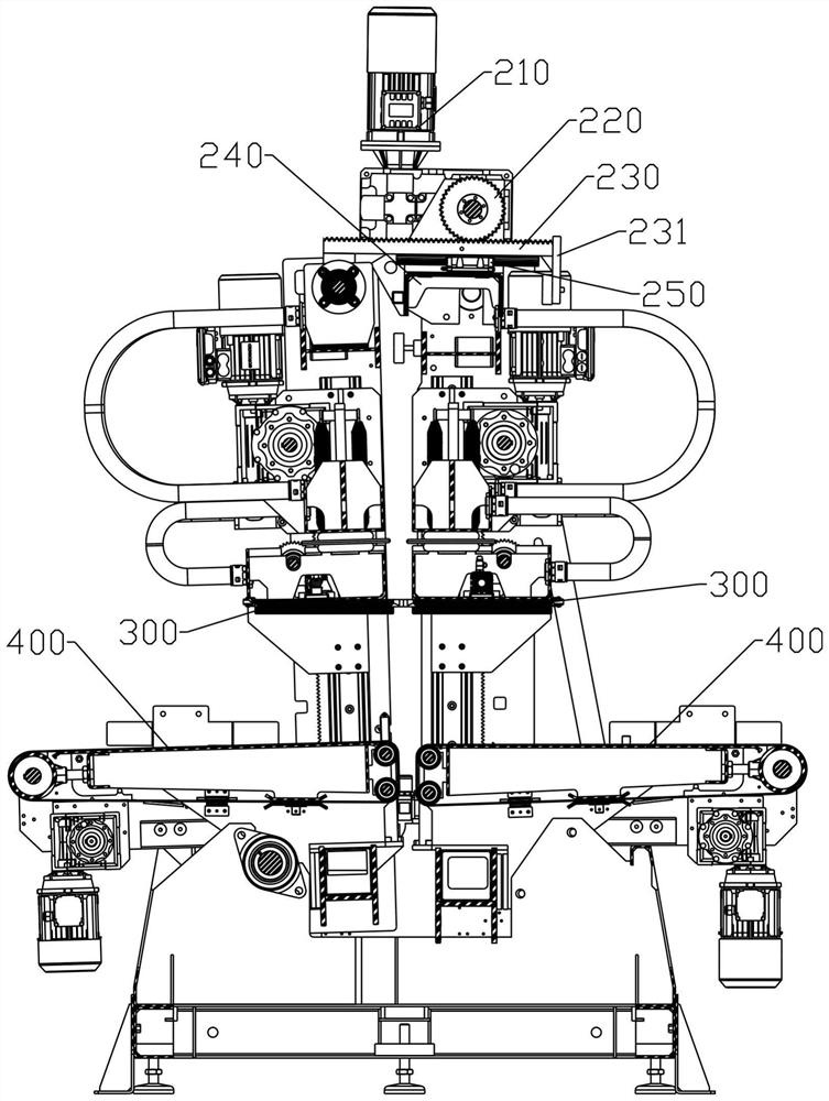
[0025] see Figure 1-4 , a slicer, comprising a frame 100 composed of a fixed frame 110 and a swing frame 120, the lower part of the swing frame 120 is rotatably connected with the fixed frame 110, and the upper part of the swing frame 120 is connected with the fixed frame 110. The swing drive assembly 200 is connected between the upper parts, and the swing drive assembly 200 is used to drive the swing frame 120 to swing around the rotational connection position with the fixed frame 11...


PUM


Abstract

The wafer separator comprises a machine frame composed of a fixed machine frame and a swing machine frame, the lower portion of the swing machine frame is rotationally connected with the fixed machine frame, a swing driving assembly is connected between the upper portion of the swing machine frame and the upper portion of the fixed machine frame, and a swing support is arranged on the fixed machine frame; a first driving motor, a first gear and a sliding rail are installed on a swing support, the first gear is connected with a first rack in a meshed mode, the first rack is connected with the sliding rail in a sliding mode, and one end of the first rack is rotationally connected to a swing rack. And then the pressing plates are driven to press the paperboard, then the first driving motor drives the first rack to move, the swing rack is driven to swing, the paperboard is pressed by the pressing plates on one side of the fixed rack and one side of the swing rack, the paperboard is torn in the swing process of the swing rack, automatic piece separation is achieved, the production efficiency is improved, and the labor intensity is reduced.

Description

technical field [0001] The invention relates to the field of carton production equipment, in particular to a slicing machine and a carton production line. Background technique [0002] In the carton packaging industry, in order to improve production efficiency and meet the performance requirements of die-cutting equipment, in the die-cutting process, a multi-mode method is often used, that is, die-cutting once and outputting multiple cardboard products. In other words, after being die-cut by the die-cutting machine, the paperboard A is output, and the paperboard A includes A1 and A2 connected together by the connection point B, wherein A1 and A2 will finally be made into independent carton products, such as Figure 5 shown. At present, to separate the cardboards connected together through multiple connection points, it is necessary to manually break the cardboard A at the connection point B to form A1 and A2, which leads to high labor intensity and low production efficiency....

Claims


Application Information

Patent Timeline
Patent Type & Authority Applications(China)
IPC IPC(8): B31B50/14
CPCB31B50/14Y02P70/50
Inventor 刘汉佳王钊荣刘志贤
Owner GUANGDONG DONGFANG PRECISION SCI & TECH CO LTD
Why Eureka
Try Eureka