Metal powder processing device for metal cutting machine
A processing device and metal powder technology, applied in metal processing machinery parts, metal processing equipment, cleaning methods and appliances, etc., can solve problems such as polluting the working environment, dust flying outside, and lack of dust collection functions
- Summary
- Abstract
- Description
- Claims
- Application Information
AI Technical Summary
Problems solved by technology
Method used
Image

Examples
Embodiment 1
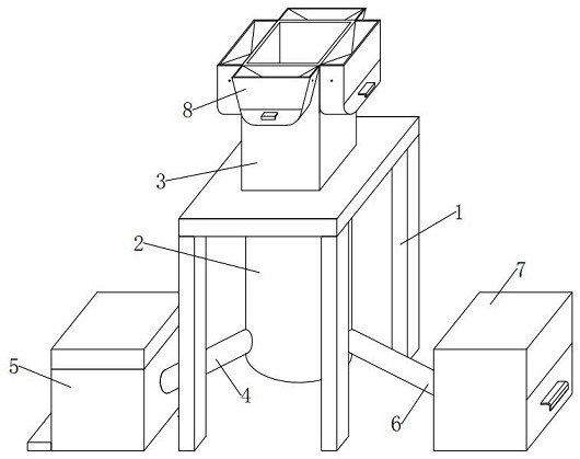
[0045] see Figure 1-3 , In an embodiment of the present invention, a metal powder processing device for a metal cutting machine includes:
[0046] The support frame 1, the center position of the inner surface of the top side of the support frame 1 is fixedly installed with the processing device body 2, and the center position of the outer surface of the top side of the support frame 1 is fixedly installed with a powder feeding hopper 3, and the appearance of the powder feeding hopper 3 is internal A hollow, up and down quadrangular prism shape, the bottom outlet of the powder hopper 3 is connected to the top inlet of the processing device body 2 through and docking, and the left part of the bottom end of the processing device body 2 is obliquely penetrated and fixedly installed with a first branch pipe 4. A dust collection chamber 5 is fixedly installed through the left end tail of the branch pipe 4, a second branch pipe 6 is installed obliquely through the right part of the ...
Embodiment 2
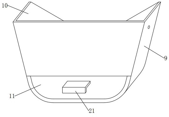
[0057] see Figure 3-4 , Figure 6-7 , the difference between the embodiment of the present invention and the embodiment 1 is that the dust guide assembly 10 includes:
[0058] Guide plate 12, the top positions of the left and right inner walls of the dust receiving shell 9 are fixedly installed obliquely with the guide plate 12, the angle between the guide plate 12 and the horizontal plane is 30°, and the rear outer surface of the guide plate 12 is fixedly installed on the outer surface of the powder hopper 3. The upper end position , the front outer surface of the guide plate 12 is fixedly installed on the upper end position of the front inner wall of the dust receiving shell 9;
[0059] The guide plate 12 here has an included angle of 30° with the horizontal plane, so that the dust floating from the top inlet of the powder hopper 3 falls into the dust receiving shell 9, and can slide up and down along the guide plate 12 to the rotating plate 14. Bottom is imported.
[00...
Embodiment 3
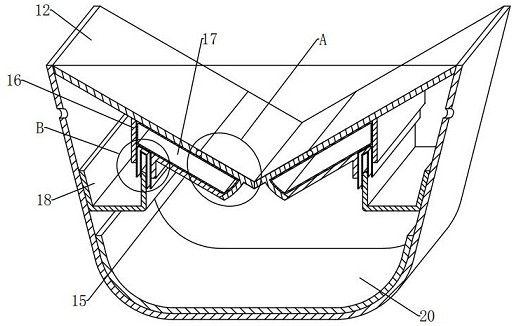
[0071] see Figure 3-7 , the difference between the embodiment of the present invention and the embodiment 1 is that the dust collecting assembly 11 includes:
[0072] The vertical plate 16, the middle end position of the bottom outer surface of the guide plate 12 is fixedly installed with the vertical plate 16 in the vertical direction, and the rear outer surface of the vertical plate 16 is also fixedly installed on the outer surface of the powder hopper 3. The front outer surface of 16 is fixedly installed on the upper end position of the front inner wall of the dust receiving shell 9, and there is a gap between the vertical plate 16 and the inclined plate 15;
[0073] The vertical plate 16 here is for the convenience of cooperating with the guide plate 12, the rotating plate 14 and the inclined plate 15 to limit and embed the air bag 17. When the rotating plate 14 is pressed and rotated downward, the air bag 17 can be squeezed to make it Trigger the guide chute 19 to slide...
PUM
 Abstract
Description
Claims
Application Information
 - Generate Ideas
- Intellectual Property
- Life Sciences
- Materials
- Tech Scout
- Unparalleled Data Quality
- Higher Quality Content
- 60% Fewer Hallucinations
Browse by: Latest US Patents, China's latest patents, Technical Efficacy Thesaurus, Application Domain, Technology Topic, Popular Technical Reports.
© 2025 PatSnap. All rights reserved.Legal|Privacy policy|Modern Slavery Act Transparency Statement|Sitemap|About US| Contact US: help@patsnap.com