Fingerprint detection device and electronic equipment

A technology for fingerprint detection and electronic equipment, applied in character and pattern recognition, instruments, computing, etc., can solve problems such as inability to image, pixel unit overexposure, light leakage, etc., to achieve improved effects, improved recognition effects, and improved imaging quality Effect

Pending Publication Date: 2022-07-08
SHENZHEN GOODIX TECH CO LTD
View PDF0 Cites 0 Cited by
  • Summary
  • Abstract
  • Description
  • Claims
  • Application Information

AI Technical Summary

Problems solved by technology

[0002] At present, the under-screen optical fingerprint detection device has been mass-produced in smart phones and other electronic products, and has been well received by users. However, when the external ambient light is strong, this part of the light will become light leakage and enter the pixels of the fingerprint detection device. unit, this part of the light leakage may make the pixel unit overexposed, and thus unable to form an image

Method used


Image

  • Fingerprint detection device and electronic equipment
  • Fingerprint detection device and electronic equipment
  • Fingerprint detection device and electronic equipment

Examples


Embodiment Construction

[0043] The technical solutions in the embodiments of the present application will be described below with reference to the accompanying drawings.

[0044] It should be understood that the embodiments of the present application can be applied to optical fingerprint systems, including but not limited to optical fingerprint recognition systems and products based on optical fingerprint imaging. The embodiments of the present application only take the optical fingerprint system as an example for description, but should not be implemented in this application. The examples constitute any limitation, and the embodiments of the present application are also applicable to other systems using optical imaging technology, and the like.

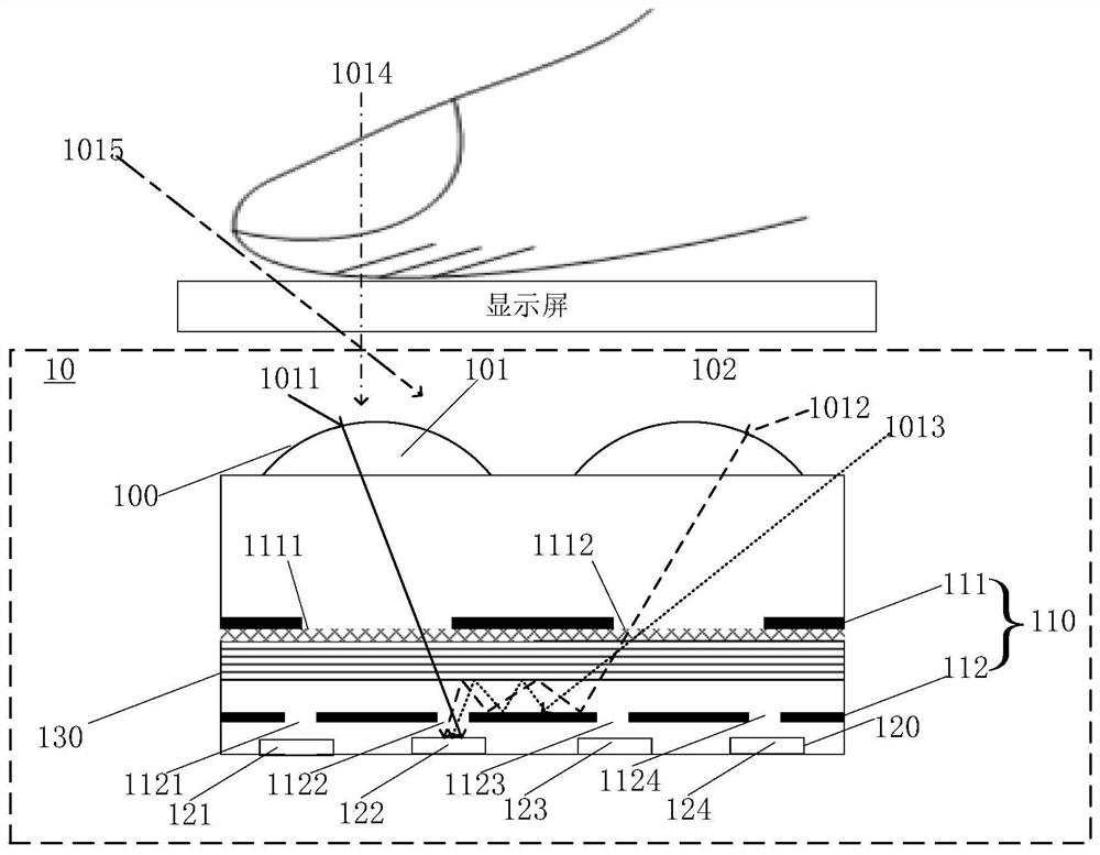
[0045] As a common application scenario, the optical fingerprint system provided in the embodiments of the present application can be applied to smart phones, tablet computers, and other mobile terminals or other electronic devices with display screens; more...


PUM


Abstract

The fingerprint detection device provided by the invention can improve the recognition effect of fingerprint detection. The fingerprint detection device is used for being arranged below a display screen of the electronic equipment, and is characterized by comprising a microlens array which comprises a plurality of microlenses; the at least two light blocking layers are arranged below the micro lens array, and each light blocking layer in the at least two light blocking layers comprises at least one first small hole corresponding to each micro lens in the micro lens array; the pixel unit array is arranged below the at least two light blocking layers, the pixel unit array comprises at least one pixel unit corresponding to each micro lens, the pixel units are used for receiving light signals which are converged by the corresponding micro lenses and are guided through first small holes in the at least two light blocking layers, and the first small holes in the at least two light blocking layers are communicated with the first small holes in the at least two light blocking layers. The bottom light blocking layer in the at least two light blocking layers is a metal layer, and the first small holes in the bottom light blocking layer are in one-to-one correspondence with the pixel units; the light filtering layer is arranged between the bottom light blocking layer and an upper light blocking layer of the bottom light blocking layer; the lateral light blocking layer is arranged on the upper surface of the non-hole-opening area of the bottom light blocking layer and located below the light filtering layer, the height of the lateral light blocking layer is larger than or equal to 90% of the distance between the bottom light blocking layer and the light filtering layer, the lateral light blocking layer comprises at least one second small hole corresponding to each micro lens, and the second small holes correspond to the micro lenses. And the size of the second small hole is larger than that of the first small hole in the bottom light blocking layer.

Description

technical field [0001] The present application relates to the technical field of optical fingerprints, and more particularly, to a fingerprint detection device and electronic equipment. Background technique [0002] At present, the under-screen optical fingerprint detection device has been mass-produced in electronic products such as smartphones, and has been well received by users. However, when the external ambient light is strong, this part of the light will become light leakage and enter the pixels of the fingerprint detection device. unit, this part of the light leakage may cause the pixel unit to be overexposed, and thus cannot be imaged. [0003] Therefore, how to improve the recognition effect of the fingerprint detection device in the strong light scene and improve the user experience is an urgent problem to be solved. SUMMARY OF THE INVENTION [0004] The embodiments of the present application provide a fingerprint detection device and electronic equipment, whic...

Claims


Application Information

Patent Timeline
Patent Type & Authority Applications(China)
IPC IPC(8): G06V40/13
CPCG06V40/13G06F18/00
Inventor 高攀吴宝全王胤祝林锋
Owner SHENZHEN GOODIX TECH CO LTD
Why Eureka
Try Eureka