Impeller assembly for axial flow compressed air pressurization in shaft seal cavity and dry gas seal structure

A dry gas seal and shaft seal technology, which is applied to parts of pumping devices for elastic fluids, engine seals, pump components, etc., can solve the problems of complicated numerical calculation and comparison process and long time for new contour search, etc. Achieve the effects of strong opening ability, high operation stability and improved gas film stability

Pending Publication Date: 2022-07-08
KUNMING UNIV OF SCI & TECH
View PDF8 Cites 0 Cited by
  • Summary
  • Abstract
  • Description
  • Claims
  • Application Information

AI Technical Summary

Problems solved by technology

The innovative design around the groove type can improve the performance and service life of the dry gas seal to a certain extent, but there are problems such as long search time for the new contour and complicated numerical calculation and comparison process.

Method used


Image

  • Impeller assembly for axial flow compressed air pressurization in shaft seal cavity and dry gas seal structure
  • Impeller assembly for axial flow compressed air pressurization in shaft seal cavity and dry gas seal structure
  • Impeller assembly for axial flow compressed air pressurization in shaft seal cavity and dry gas seal structure

Examples


Embodiment 1

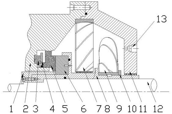
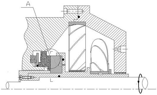
[0054] The impeller assembly for the axial flow pressurization in the shaft seal cavity includes a stationary impeller 7 and a guide impeller 9. The guide impeller 9 and the static impeller 7 are sequentially arranged along the flow direction of the sealing medium in the shaft seal cavity, and the guide impeller 9, the static impeller There is a gap between the impellers 7, the guide impeller 9 rotates with the shaft 12, the outer edge of the stationary impeller 7 is fixed on the inner wall of the shaft seal cavity, the shaft 12 passes through the central mounting hole of the stationary impeller 7, and the central mounting hole of the stationary impeller 7 is provided with Spiral seal, the vane direction of the stationary impeller 7 is opposite to the vane direction of the guide impeller 9 .

Embodiment 2

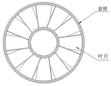
[0056] On the basis of Embodiment 1, the outer edge of the stationary impeller 7 is provided with a cantilever, and the outer edge of the stationary impeller 7 is fixed on the inner wall of the shaft seal cavity through the cantilever.

Embodiment 3

[0058] Except that the number of blades of the guide impeller 9 is 8 and the number of blades of the stationary impeller 7 is 15, the rest is the same as that of the second embodiment.


PUM


Abstract

The invention discloses an impeller assembly for axial flow compressed air pressurization in a shaft seal cavity. The impeller assembly comprises a static impeller and a flow guide impeller. The invention further discloses a dry gas sealing structure for axial flow compressed air pressurization in the shaft sealing cavity, and the dry gas sealing structure comprises the impeller assembly and further comprises an axial positioning ring, a sealing end cover, a working spring, a push ring, a static ring, a movable ring, a movable ring seat and a sealing chamber. After a gas sealing medium is guided and pressurized, the pressure of the gas sealing medium at the gas inlet of the movable ring is improved, the opening force and the gas film rigidity are also increased, and then the opening capacity and the external interference resistance of the gas film are improved; the formed gas film effectively overcomes the elastic force and fluid static pressure of the working spring, so that the contact probability between the two sealing rings is reduced, the frictional wear phenomenon is reduced, finally, the purposes of improving the dry gas sealing stability and prolonging the service life are achieved, and the dry gas sealing structure is particularly suitable for low-pressure and high-speed special working conditions.

Description

technical field [0001] The invention belongs to the technical field of mechanical seals, and in particular relates to an impeller assembly and a dry gas seal structure for supercharging axial flow pressure in a shaft seal cavity. Background technique [0002] With the development of the industry, all industries are faced with the tasks of equipment optimization and technology update. As a non-contact seal, dry gas seals have the advantages of long service life, low energy consumption and low leakage rate, and are widely used in petrochemical, oil and gas transportation, and energy power generation industries. The working efficiency of the dry gas seal depends on the state of the gas film between the sealing end faces. Good gas film stability means that the seal can better adapt to the beating and deformation of the sealing end face in the face of sudden changes in working conditions, reducing the probability of friction of the sealing ring. , effectively prolong the service...

Claims


Application Information

Patent Timeline
Patent Type & Authority Applications(China)
IPC IPC(8): F04D29/30F04D29/44F16J15/34
CPCF04D29/30F04D29/444F16J15/344F16J15/3464Y02E10/20
Inventor 许恒杰岳迎港宋鹏云
Owner KUNMING UNIV OF SCI & TECH
Why Eureka
Try Eureka