Automatic oiling device for bearing machining

A bearing processing and automatic technology, which is applied in the field of bearing processing, can solve the problems of unfavorable packaging operation due to oil film thickness, complicated oil film forming steps, and high labor intensity of workers, so as to improve the excessive amount of oil, reduce the cost of materials, and avoid The effect of spraying dead angle

Active Publication Date: 2022-07-08
江苏泽恩机械科技有限公司
View PDF6 Cites 0 Cited by
  • Summary
  • Abstract
  • Description
  • Claims
  • Application Information

AI Technical Summary

Problems solved by technology

[0003] After the bearing is processed, it needs to be treated with anti-oxidation and corrosion on the surface. Therefore, it is generally necessary to oil the bearing. The oil layer is used to form a surface diaphragm to prevent the bearing from being directly oxidized by contact with water vapor in the air. The existing oiling method is generally by dipping. Liquid type or manual spraying oiling, immersion type means that the bearing is put into the oil pool by using the transmission component or manually and then pulled out to make the surface covered with a thick oil layer, which requires subsequent draining and cleaning, which consumes a lot of oil and has a thicker oil film layer. Thickness is not conducive to subsequent packaging operations, while manual spraying and oiling is slow and inefficient, and the labor intensity of workers is high, and the processing and production costs are high
[0004] In view of this, the existing problems are studied and improved, and an automatic oiling device for bearing processing is provided to solve the existing problems of low automation of bearing processing oiling and complicated oil film forming steps. Through this technology, To achieve the purpose of solving problems and improving practical value

Method used


Image

  • Automatic oiling device for bearing machining
  • Automatic oiling device for bearing machining
  • Automatic oiling device for bearing machining

Examples


Embodiment Construction

[0031] In order to make the objectives, technical solutions and advantages of the present invention clearer, the present invention will be further described in detail below with reference to the specific embodiments and the accompanying drawings. It should be noted that the embodiments of the present invention and the features in the embodiments may be combined with each other under the condition of no conflict.

[0032] The following describes an automatic oiling device for bearing processing provided by some embodiments of the present invention with reference to the accompanying drawings.

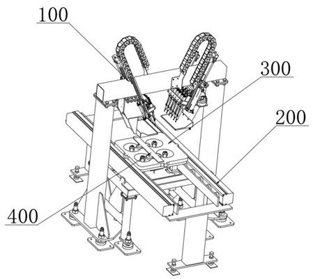
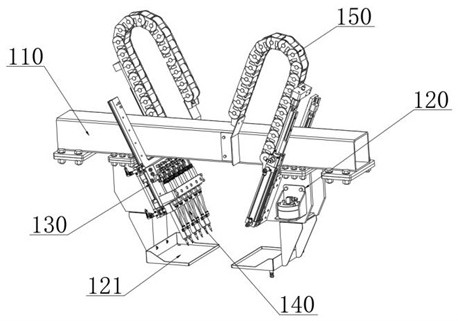
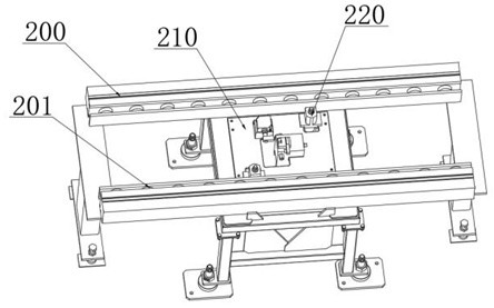
[0033] combine Figure 1-Figure 7 As shown, an automatic oiling device for bearing processing provided by the present invention includes: a spraying frame assembly 100, a conveying frame 200, a material tray 300 and an oil film forming assembly 400, the inner side of the conveying frame 200 is fixedly installed with a lifting platform 210, The spraying rack assembly 100 and the conveying...


PUM


Abstract

The invention relates to the technical field of bearing machining, in particular to an automatic oiling device for bearing machining, which comprises a spraying frame assembly, a conveying frame, a material tray and an oil film forming assembly, a jacking table is fixedly mounted on the inner side of the conveying frame, the spraying frame assembly and the conveying frame are fixed on the ground, and the spraying frame assembly is located right above the jacking table; a jacking push rod is fixedly installed on the surface of the jacking table, and a plurality of driving rollers are installed on the inner side of the conveying frame in a transmission mode. According to the device, an automatic atomization spraying and bearing seat moving structure is arranged, oil liquid is atomized and sprayed through an atomization spray head, so that the oil liquid is dispersed into small-particle atomized molecules under the high-pressure effect to be evenly distributed on the surface of a bearing, and the bearing is driven by an oil film forming assembly to rotate in a containing groove; and liquid drops attached to the surface are uniformly dispersed, so that oil films on the moving contact surface and the outer surface are uniformly formed, the oil film forming thickness is small, subsequent cleaning steps are reduced, the production cost is reduced, and the production efficiency is improved.

Description

technical field [0001] The invention relates to the technical field of bearing processing, in particular to an automatic oiling device for bearing processing. Background technique [0002] Bearing is an important part of contemporary mechanical equipment. Its main function is to support the mechanical rotating body, reduce the friction coefficient during its movement, and ensure its rotation accuracy. [0003] After the bearing is processed, the surface needs to be treated to prevent oxidation and rust. Therefore, it is generally necessary to oil the bearing and use the oil layer to form a surface diaphragm to prevent the bearing from directly contacting and oxidizing with water vapor in the air. The existing oiling method is generally by immersion. Liquid or manual spraying and oiling, immersion means that the bearing is covered with a thick oil layer by using the transmission component or manually to put the bearing into the oil pool and remove it, which requires subsequen...

Claims


Application Information

Patent Timeline
IPC IPC(8): B05B9/04B05B13/02B05B15/68
CPCB05B9/0423B05B13/0235B05B15/68B05B13/0292Y02P70/10
Inventor 王俊凤袁红雷
Owner 江苏泽恩机械科技有限公司
Why Eureka
Try Eureka