Novel pad dyeing machine for microfiber leather and pad dyeing process of novel pad dyeing machine
A technology of microfiber leather and pad dyeing machine, which is applied in the direction of processing textile material cleaning device, liquid/gas/vapor fabric processing, and textile material processing equipment configuration, etc. Product qualification rate and other issues, to achieve the effect of simple and fast operation, improved cleaning efficiency, and convenient use
- Summary
- Abstract
- Description
- Claims
- Application Information
AI Technical Summary
Problems solved by technology
Method used
Image
Examples
Embodiment 1
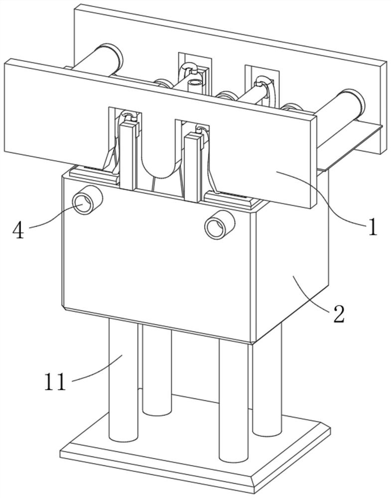
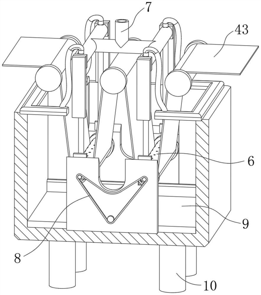
[0032] see Figure 1-Figure 3, a new type of pad dyeing machine for microfiber leather in the figure, including a body 1, a pad dyeing device 6, a cleaning device 7 and a linkage device 8, the body 1 is fixedly connected with a dye box 2, and the body 1 is rotatably connected with multiple groups of The driving roller 3 used to drive the microfiber leather 43 for transmission pad dyeing, the dye box 2 is fixedly connected with a liquid injection pipe 4 and a liquid discharge pipe 5, and the pad dyeing device 6 is installed in the dye box 2 to drive the microfiber leather. 43 is immersed in the dye box 2 for pad dyeing, and the cleaning device 7 is installed in the dye box 2 for cleaning the dye box 2 and the pad dyeing device 6 when the drain pipe 5 is opened, and the linkage device 8 is installed in the dye box 2 Inside, it is used to stop cleaning when the drain pipe 5 is closed, and when the pad dyeing device 6 drives the microfiber leather 43 for pad dyeing, it is linked t...
Embodiment 2
[0039] see Figure 2-Figure 3 Illustrating Embodiment 2, this embodiment further describes Embodiment 1. The cleaning device 7 in the figure includes a lifting plate 9 slidably connected to the inner wall of the dye box 2, and a plurality of lifting rods 10 are fixedly connected to the bottom surface of the lifting plate 9. The lifting rod 10 runs through the bottom end of the dye box 2 and is slidably connected with the dye box 2. The body 1 is fixedly connected with a fixed tube 11 that is slidably connected with the lifting rod 10, and the bottom end of the lifting rod 10 is fixedly connected with the body 1. Fixed connection The first spring 12 of the dye box 2 is provided with a cleaning mechanism 13 for cleaning the pad dyeing device 6 and the lifting plate 9 .
[0040] see Figure 4-Figure 5 , the pad dyeing device 6 in the figure includes a drive tube 14 that is connected to the microfiber leather 43, both sides of the lifting plate 9 are fixedly connected with side p...
Embodiment 3
[0045] see Figure 4-Figure 9 Embodiment 3 is described. This embodiment further describes Embodiment 1. The cleaning mechanism 13 in the figure includes a water pipe 23 that is fixedly installed on the body 1, the top of the dye box 2 is fixedly connected with a spray box 24, and the driving pipe 14 A plurality of first through holes 25 are opened on the top, and a plurality of second through holes 26 are opened on the side of the device pipe 16 for spraying the side plate 15. After the position is set, the communication piece 27 that makes the water pipe 23 communicate with the shower box 24 , the first through hole 25 and the second through hole 26 is all connected.
[0046] see Figure 4-Figure 9 , the connecting member 27 in the figure includes a lifting pipe 28 fixedly installed on the upper end of the device pipe 16, the lifting pipe 28 penetrates the water pipe 23, and is slidably connected with the water pipe 23, and the top of the lifting pipe 28 is fixedly connecte...
PUM
 Abstract
Description
Claims
Application Information
 - R&D Engineer
- R&D Manager
- IP Professional
- Industry Leading Data Capabilities
- Powerful AI technology
- Patent DNA Extraction
Browse by: Latest US Patents, China's latest patents, Technical Efficacy Thesaurus, Application Domain, Technology Topic, Popular Technical Reports.
© 2024 PatSnap. All rights reserved.Legal|Privacy policy|Modern Slavery Act Transparency Statement|Sitemap|About US| Contact US: help@patsnap.com


