Automatic part taking equipment for high-speed machining of valve body part
A technology for automatically picking up parts and components, which is applied in the directions of conveyor objects, transportation and packaging, loading/unloading, etc. It can solve the problems of labor-intensive, low labor efficiency, and unfavorable long-term development of enterprises, so as to achieve safe and reliable work processes and improve work efficiency. The effect of efficiency
- Summary
- Abstract
- Description
- Claims
- Application Information
AI Technical Summary
Problems solved by technology
Method used
Image

Examples
Embodiment 1
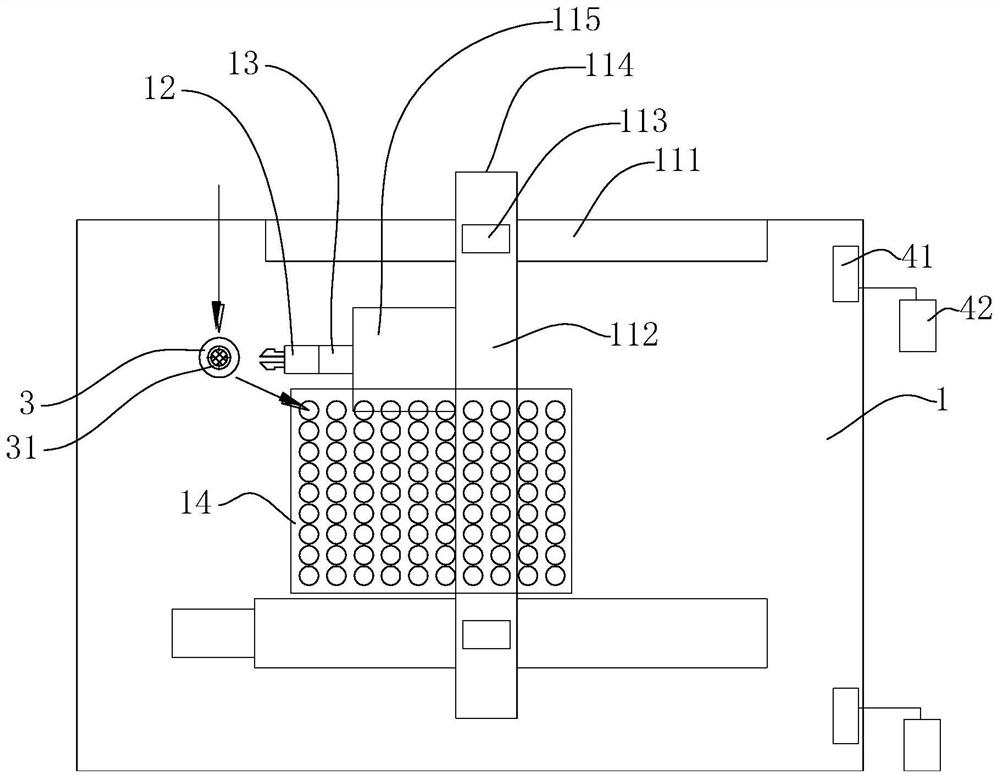
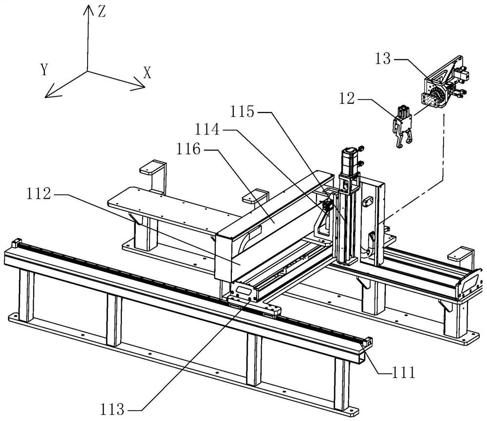
[0024] An automatic pick-up device for high-speed processing of valve body parts includes a pick-and-place mechanism 1 . refer to figure 1 , image 3 and Figure 4 As shown, the pick-and-place mechanism 1 includes a three-axis moving mechanism 11 of a gantry 112 structure, a thumb cylinder 12 , a right-angle rotation mechanism 13 and a tray support table 14 . The three-axis moving mechanism 11 includes two parallel moving rails 111 , an X-direction moving table 113 mounted on the moving rails 111 through two ends of the gantry 112 respectively, and a Y-direction moving horizontally at the position of the beam 116 of the gantry 112 The moving table 114 , the Z-direction moving table 115 vertically moving on the beam 116 of the gantry 112 , and the thumb cylinder 12 are installed on the Z-direction moving table 115 through the right-angle rotation mechanism 13 . The three-axis moving mechanism 11 is a mechanical device that is widely used in machining factories on the market,...
Embodiment 2
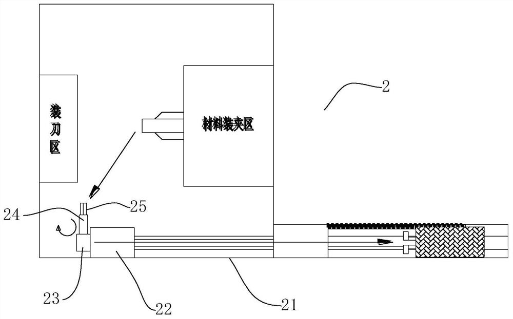
[0029] In order to facilitate processing and transportation and improve the transportation distance, a clamping and moving mechanism 2 is also included. refer to figure 2 As shown, the clamping and moving mechanism 2 includes a linear slide rail 21, a mover 22, an X-axis rotation mechanism 23, a Y-axis rotation mechanism 24, and a gripper cylinder 25. The mover 22 is assembled on the linear slide rail 21 and moves back and forth to the desired position. The X-axis rotation mechanism 23 is mounted on the mover 22 and used to drive the gripper cylinder 25 to rotate around the X-axis to the desired position, and the Y-axis rotation mechanism 24 is mounted on the X-axis rotation mechanism 23 and used to drive the gripper cylinder 25 Rotate around the Y axis to the desired position. For the X-axis rotation mechanism 23 and the Y-axis rotation mechanism 24, servo motor devices are used. Similarly, the right-angle rotation mechanism 13 in Embodiment 1 can also be referred to, that ...
Embodiment 3
[0032] refer to Figure 4 and Figure 5 The gripper cylinder 25 or thumb cylinder 12 includes two gripper jaws 51 , a mounting seat 52 , a cylinder 53 , and an auxiliary spring 54 , the two gripping jaws 51 are rotatably mounted on the mounting seat 52 and are powered by the cylinder The opening and closing action is performed by driving, and the auxiliary spring 54 is connected to the inner side of the two clamping jaw parts 51 to provide the elastic force for restoring the opening and closing. An air passage 61 is provided on the gripper portion 51 and an air bag 62 is connected to the outlet of the air passage 61 . On the basis of the above structure, a layer of flexible silica gel can also be coated and fixed on the outer layer of the airbag 62 .
[0033]The cylinder 53 is driven by power so that the clamping jaws 51 can open and close, so as to complete the clamping of the workpiece 7 . In the third embodiment, in order to improve the clamping reliability of the workpi...
PUM
 Abstract
Description
Claims
Application Information
 - R&D
- Intellectual Property
- Life Sciences
- Materials
- Tech Scout
- Unparalleled Data Quality
- Higher Quality Content
- 60% Fewer Hallucinations
Browse by: Latest US Patents, China's latest patents, Technical Efficacy Thesaurus, Application Domain, Technology Topic, Popular Technical Reports.
© 2025 PatSnap. All rights reserved.Legal|Privacy policy|Modern Slavery Act Transparency Statement|Sitemap|About US| Contact US: help@patsnap.com