Magnetic suspension type shock absorber for new-energy automobile

A new energy vehicle and magnetic levitation technology, applied in the auxiliary field of cargo boxes, can solve the problems of low strength, unfavorable cargo transportation safety, deformation, etc., and achieve the effects of ensuring safe use, improving the scope of application, and being convenient to use.

Active Publication Date: 2019-09-20
蒙阴县鹏程万里车辆有限公司
View PDF7 Cites 0 Cited by
  • Summary
  • Abstract
  • Description
  • Claims
  • Application Information

AI Technical Summary

Problems solved by technology

[0002] At present, with the popularization of new energy vehicles, new energy vehicles are often used in cargo transportation. Containers are often used for loading, and containers with closed boxes are generally equipped with a rectangular door frame. A pair of doors can be turned into the plane of the door frame to close the cargo box, and it is also convenient to lead to the inside of the cargo box. For economic considerations, most of today's cargo boxes are made of materials with low strength. When transporting some bags or For bulk cargo in other packages, the container door is prone to receive a large extrusion force. Due to the low strength of the components, the door frame and the container door will be deformed under the extrusion force, which is not conducive to the safety of cargo transportation. Therefore, a new energy vehicle magnetic suspension shock absorber is needed to increase the safety of cargo transportation

Method used


Image

  • Magnetic suspension type shock absorber for new-energy automobile
  • Magnetic suspension type shock absorber for new-energy automobile
  • Magnetic suspension type shock absorber for new-energy automobile

Examples


Embodiment Construction

[0012] The following will clearly and completely describe the technical solutions in the embodiments of the present invention with reference to the accompanying drawings in the embodiments of the present invention. Obviously, the described embodiments are only some, not all, embodiments of the present invention. Based on the embodiments of the present invention, all other embodiments obtained by persons of ordinary skill in the art without making creative efforts belong to the protection scope of the present invention.

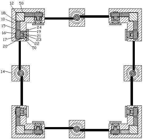
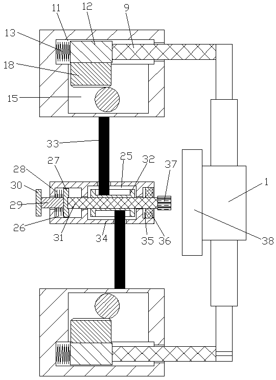
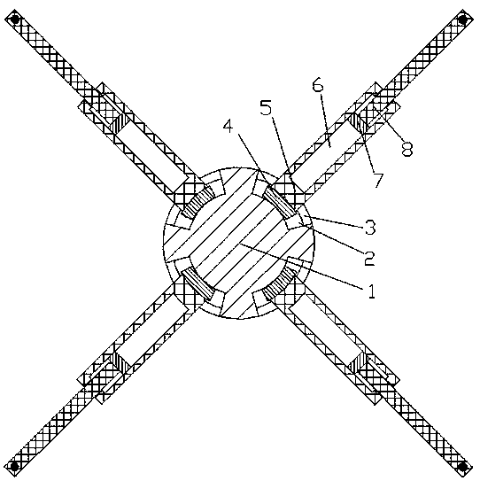
[0013] see Figure 1-3 , an embodiment provided by the present invention: a magnetic levitation shock absorber for a new energy vehicle, comprising a circular connection block 1, the rear end surface of the circular connection block 1 is fixedly connected with an anti-extrusion plate 38, the circular There is an annular connecting space 2 evenly distributed at the four corners of the connecting block 1, and an annular connecting groove 3 is arranged at the end...


PUM


Abstract

The invention discloses a magnetic suspension type shock absorber for a new-energy automobile. The magnetic suspension type shock absorber for the new-energy automobile comprises circular connecting blocks, wherein anti-extrusion plates are fixedly connected to the back end surfaces of the circular connecting blocks; one ends, far away from circle centers, of telescopic rods penetrate through the inner walls of telescopic spaces so as to outwards extend and are hinged with connecting rods extending backwards; clamping blocks are arranged at the positions corresponding to the back sides of the connecting rods; each two adjacent clamping blocks are connected through contraction device; and one ends, far away from transmission gears, of fixed connecting shafts penetrate through the inner walls of spline grooves and are fixedly connected with friction plates. During the work of the magnetic suspension type shock absorber for the new-energy automobile provided by the invention, the angles of telescopic sleeve rods can be adjusted along with the position changes of the clamping blocks at four corner parts, and meanwhile, the distance adjustment can be carried out, so that the requirements on the positions of the clamping blocks during the use of different containers are met, and the application range of the device is improved; and the larger the extrusion forces stressed on the anti-extrusion plates, the larger the friction forces are, so that the occurrence of the phenomenon that the device falls off when container doors are stressed by the larger extrusion forces is prevented, and the safety use of the device is ensured.

Description

technical field [0001] The invention relates to the field of cargo box auxiliary technology, in particular to a magnetic suspension shock absorber for a new energy vehicle. Background technique [0002] At present, with the popularization of new energy vehicles, new energy vehicles are often used in cargo transportation. Containers are often used for loading, and containers with closed boxes are generally equipped with a rectangular door frame. A pair of doors can be turned into the plane of the door frame to close the cargo box, and it is also convenient to lead to the inside of the cargo box. For economical considerations, today's cargo boxes are mostly made of low-strength materials. When transporting some bags or For bulk cargo in other packages, the container door is prone to receive a large extrusion force. Due to the low strength of the components, the door frame and the container door will be deformed under the extrusion force, which is not conducive to the safety of...

Claims


Application Information

Patent Timeline
Patent Type & Authority Applications(China)
IPC IPC(8): B65D90/00
CPCB65D90/00B65D2590/0041
Inventor 周青金慧丽
Owner 蒙阴县鹏程万里车辆有限公司
Why Eureka
Try Eureka