Eureka AIR delivers breakthrough ideas for toughest innovation challenges, trusted by R&D personnel around the world.

Two-dimensional nozzle flying lap joint outer cover structure

A binary nozzle and cover technology, which is applied to aircraft, aircraft parts, power units on aircraft, etc., can solve the problem of large deformation and stress concentration in the slotted area, which does not meet the integrated design of flight and engine, and is unfavorable for the rear of the aircraft. Body stealth and other issues, to achieve the effect of improving stealth effect, avoiding motion interference, and improving stealth performance

Pending Publication Date: 2022-06-28
AECC SHENYANG ENGINE RES INST
View PDF0 Cites 0 Cited by
  • Summary
  • Abstract
  • Description
  • Claims
  • Application Information

AI Technical Summary

Problems solved by technology

[0005] (1) Reliability issues: In order to meet the air volume required for starting the engine, the elastic sheet of the compression contact type is slit. The elastic sheet is affected by the external flow field and the elastic compression preload, and the slit area is prone to large Deformation and stress concentration, resulting in cracks;
[0007] At present, there is no dual nozzle flying-engine overlapping cover in China. If an elastic ring is used to overlap the tail cover, there will be overlapping steps, which does not meet the integrated design of flying and launching, and is not conducive to the stealth of the rear body of the aircraft; the area of ​​the elastic ring is relatively small. Large, if the stealth coating will further increase the weight

Method used


Image

  • Two-dimensional nozzle flying lap joint outer cover structure
  • Two-dimensional nozzle flying lap joint outer cover structure
  • Two-dimensional nozzle flying lap joint outer cover structure

Examples


Embodiment Construction

[0034] In order to make the objectives, technical solutions and advantages of the implementation of the present application clearer, the technical solutions in the embodiments of the present application will be described in more detail below with reference to the accompanying drawings in the embodiments of the present application. Throughout the drawings, the same or similar reference numbers refer to the same or similar elements or elements having the same or similar functions. The described embodiments are some, but not all, embodiments of the present application. The embodiments described below with reference to the accompanying drawings are exemplary, and are intended to be used to explain the present application, but should not be construed as a limitation to the present application. Based on the embodiments in the present application, all other embodiments obtained by those of ordinary skill in the art without creative work fall within the protection scope of the present...


PUM


Abstract

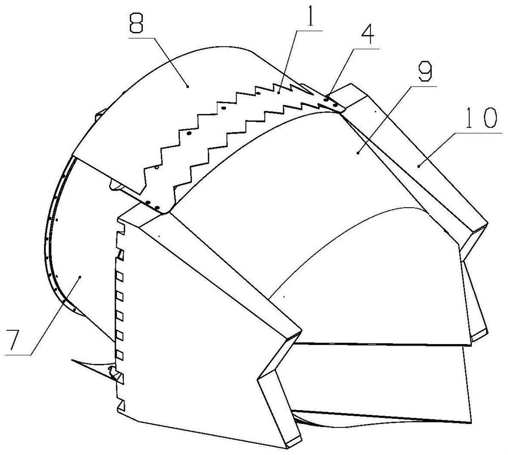
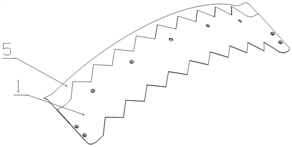
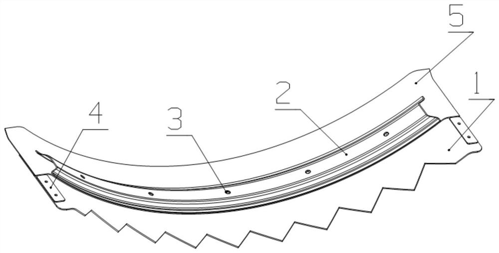
The invention belongs to the field of aero-engines, and particularly relates to a two-dimensional nozzle flying lap joint outer cover structure which mainly comprises an arc-sheet-shaped outer shell and an inner shell, the front end and the rear end of the outer shell are in sawtooth shape modification, the inner shell is located on the inner side of the outer shell, and a part of overlapping lap joint area is formed between the inner shell and the outer shell. The rear end of the outer shell and the front end of the outer adjusting piece are in lap joint and have a gap, movement interference is avoided, and meanwhile an airflow channel for exchanging an engine compartment and outflow is formed. When the state of the spray pipe is adjusted and changed, the flying lap joint outer cover keeps a good lap joint relation with the tail cover and the outer adjusting piece all the time, the good rectification effect of the flying lap joint outer cover is guaranteed, and the requirement for invisibility of an aircraft in the forward direction and the requirement for invisibility of an engine in the backward direction are met.

Description

technical field [0001] The application belongs to the field of aero-engines, and in particular relates to a structure of a binary nozzle flying hair lap joint cover. Background technique [0002] The flying hair lap cover structure of the military aero-engine is used as a component of the lap joint between the engine and the rear fuselage of the aircraft. It is an important component system of modernization, which is exposed outside the aircraft and engine body, and should also have the function of stealth. [0003] The existing flying hair lap joint outer cover structure scheme is mainly based on the compression contact type elastic sheet scheme. Taking the conventional axisymmetric nozzle scheme as an example, the flying hair lap cover structure scheme is mainly composed of a support ring structure and an elastic sheet. The support ring is fixed on the mounting seat of the cylinder casing through the support rod, and the elastic sheet is fixed on the support ring. . Whe...

Claims


Application Information

Patent Timeline
IPC IPC(8): B64D29/06B64D29/04
CPCB64D29/06B64D29/04B64U20/10
Inventor 任利锋卢浩浩吴长方王瑞祥王佳磊石峰
Owner AECC SHENYANG ENGINE RES INST
Why Eureka
Eureka Blog
Learn More