
Long and thin centrifugal casting pipe shot blasting sand removing device and method suitable for production line

A technology of centrifugal casting pipe and cleaning device, which is applied in the direction of used abrasive processing devices, metal processing equipment, manufacturing tools, etc., can solve the problems of unsuitable and difficult to completely remove shot blasting sand, and reduce the floor space , to avoid process division processing, the effect of small environmental pollution

Active Publication Date: 2022-06-28
HENAN INST OF ENG
View PDF10 Cites 0 Cited by
  • Summary
  • Abstract
  • Description
  • Claims
  • Application Information

AI Technical Summary

Problems solved by technology

[0005] Aiming at the technical problem that the existing shot blasting sand removal method in the centrifugal casting pipe is difficult to completely remove the shot blasting sand, or the existing shot blasting sand removal device is not suitable for setting up a centrifugal casting pipe production line, the present invention proposes a slender Device and method for removing shot blasting sand in centrifugal casting pipe

Method used


Image

  • Long and thin centrifugal casting pipe shot blasting sand removing device and method suitable for production line
  • Long and thin centrifugal casting pipe shot blasting sand removing device and method suitable for production line
  • Long and thin centrifugal casting pipe shot blasting sand removing device and method suitable for production line

Examples


Embodiment 1

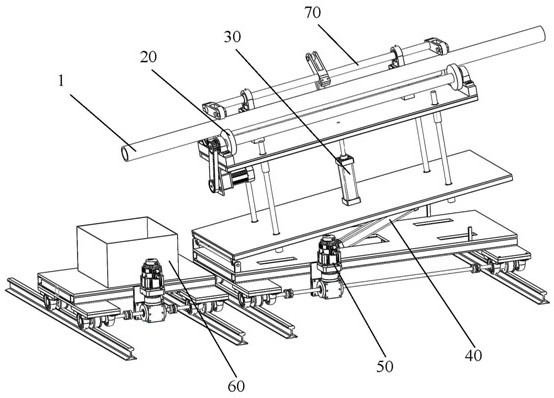
[0056] like Figure 3-8 As shown, the present application discloses a shot blasting sand removal device for elongated centrifugal casting pipes suitable for production lines, comprising a first guide rail 601 and a second guide rail 501, the first guide rail 601 and the second guide rail 501 are arranged in parallel, The first guide rail 601 is slidably provided with a recovery mechanism 60 for collecting shot blasting sand flowing out of the centrifugal casting tube. That is to say, the shot blasting sand removed from the centrifugal casting tube can be collected uniformly by the recovery mechanism, so as to prevent the shot blasting sand from falling on the ground, and at the same time facilitate the centralized treatment of the subsequent shot blasting sand.

[0057] Specifically, the recovery mechanism 60 includes a first bottom plate 602, the upper part of the first bottom plate 602 is provided with a recovery box 603 for collecting shot blasting sand, the first bottom pl...

Embodiment 2

[0068] like Figure 8 and Figure 9 As shown, the present application also discloses a method for removing shot blasting sand in a slender centrifugal casting pipe suitable for a production line, comprising the following steps:

[0069] S0. Each device is adjusted to the initial state, the tilting member is retracted, the tilting mechanism is in a horizontal state, the lifting mechanism is lowered, and the pressing mechanism is in an open state, and the centrifugal casting pipe is located on the shelf;

[0070] S1. After the components arranged on the second guide rail move to the feeding position along the second guide rail, the lifting mechanism lifts up the centrifugal casting tube and leaves the shelf, and then the lifting mechanism returns to the starting position along the second guide rail under the driving of the tilting mechanism. That is to say, at the beginning of the operation, the centrifugal casting tube is in the waiting position for feeding, and the pinch whee...


PUM

PropertyMeasurementUnit
lengthaaaaaaaaaa

Abstract

The invention provides a slender centrifugal casting pipe shot blasting sand removing device and method suitable for a production line, the device comprises a first guide rail and a second guide rail, the first guide rail and the second guide rail are arranged in parallel, a recycling mechanism is slidably arranged on the first guide rail, an inclination mechanism is slidably arranged on the second guide rail, and a lifting mechanism is arranged on the inclination mechanism; the lifting mechanism is provided with a rotating mechanism and a pressing mechanism, and the rotating mechanism is matched with the pressing mechanism. The inclination angle of the centrifugal casting pipe can be adjusted through the inclination mechanism, meanwhile, the rotation mechanism and the pressing mechanism are matched to achieve the inclined rotation action of the centrifugal casting pipe, then residual shot blasting sand in the centrifugal casting pipe can flow out under the dual action of gravity and tangential force of the inner wall of the pipe, shot blasting sand recycling is achieved, and accumulation and retention of the shot blasting sand are avoided; the cleaning effect is good, environmental pollution is small, and the whole device is compact in design and very suitable for building a centrifugal casting pipe production line.

Description

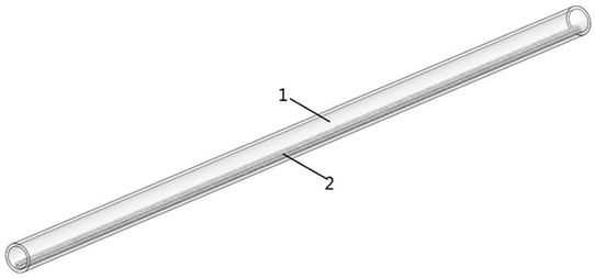
technical field [0001] The invention relates to the technical field of centrifugal casting pipe production, in particular to a shot blasting sand removing device and method for a slender centrifugal casting pipe suitable for a production line. Background technique [0002] Centrifugal cast pipe belongs to a kind of seamless metal pipe with an outer diameter of about 50mm to 200mm and a length of about 3m to 5m, such as figure 1 shown, belonging to the slender tube. The centrifugal casting tube is formed by horizontal centrifugal casting. The inner surface roughness of the formed tube is relatively large, and there are burrs at the mouth of the tube, such as figure 2 shown. The outer surface of the pipe needs to be shot blasted. Due to the long length of the pipe, horizontal shot blasting is adopted, that is, the pipe is placed horizontally on the conveying track of the horizontal shot blasting machine, and the pipe is driven by the conveying track into the horizontal sh...

Claims


Application Information

Patent Timeline
Patent Type & Authority Applications(China)
IPC IPC(8): B24C1/08B24C3/32B24C3/18B24C9/00
CPCB24C1/08B24C3/325B24C3/18B24C9/00B24C9/006Y02P70/10
Inventor 李振杰汤安鹿怀庆张红松王鑫宋艳李立琳付永辉何林东张文斌
Owner HENAN INST OF ENG
Learn More