
Fixture for welding positioning of power distribution cabinet

A welding positioning and power distribution cabinet technology, which is applied in welding equipment, auxiliary welding equipment, welding/cutting auxiliary equipment, etc., can solve the cabinet deviation of the power distribution cabinet, poor cabinet stability of the power distribution cabinet, Problems such as poor fixing effect of the cabinet body of the power distribution cabinet, to achieve the effect of improving the fixing effect, improving stability, and improving welding quality

Pending Publication Date: 2022-06-28
山东科美帝电气科技有限公司
View PDF0 Cites 0 Cited by
  • Summary
  • Abstract
  • Description
  • Claims
  • Application Information

AI Technical Summary

Problems solved by technology

[0003] However, the devices in the prior art still have the following problems: 1. The existing device has a poor fixing effect on the cabinet body of the power distribution cabinet, thereby affecting the welding quality of the cabinet body of the power distribution cabinet; 2. The positioning of the existing device The effect is not good, so the cabinet body of the power distribution cabinet is prone to shift during installation; 3. The existing device has poor stability to the cabinet body of the power distribution cabinet

Method used


Image

  • Fixture for welding positioning of power distribution cabinet
  • Fixture for welding positioning of power distribution cabinet
  • Fixture for welding positioning of power distribution cabinet

Examples


Embodiment Construction

[0029] In order to make the technical means, creative features, achievement goals and effects realized by the present invention easy to understand, the present invention will be further described below with reference to the specific embodiments.

[0030] In the description of the present invention, it should be noted that the terms "upper", "lower", "inner", "outer", "front end", "rear end", "two ends", "one end" and "the other end" The orientation or positional relationship indicated by etc. is based on the orientation or positional relationship shown in the accompanying drawings, and is only for the convenience of describing the present invention and simplifying the description, rather than indicating or implying that the indicated device or element must have a specific orientation, with a specific orientation. The orientation configuration and operation are therefore not to be construed as limitations of the present invention. Furthermore, the terms "first" and "second" are...


PUM


Abstract

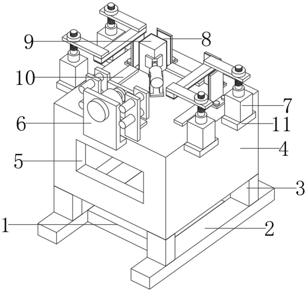
The invention discloses a power distribution cabinet welding positioning clamp which comprises a base, the left end and the right end of the base are fixedly connected with first supporting plates, the front portions and the rear portions of the upper ends of the two first supporting plates are fixedly connected with supporting legs, and the upper ends of the four supporting legs are jointly and fixedly connected with a workbench. Through grooves are formed in the middle of the front end and the middle of the rear end of the workbench, two limiting mechanisms are symmetrically and fixedly connected to the left portion and the right portion of the upper end of the workbench, a positioning device is fixedly connected to the rear portion of the upper end of the workbench, and a pushing mechanism is fixedly connected to the upper portion of the front end of the workbench. The upper portion of the left end and the upper portion of the right end of the workbench are each fixedly connected with two first supporting blocks, the middles of the upper ends of the two longitudinal first supporting blocks are jointly and fixedly connected with pressing devices, and the two pressing devices are symmetrically installed. According to the clamp for welding and positioning of the power distribution cabinet, the whole device can stably clamp the power distribution cabinet, and the welding quality of the power distribution cabinet is improved.

Description

technical field [0001] The invention relates to the technical field of welding positioning of power distribution cabinets, in particular to a fixture used for welding positioning of power distribution cabinets. Background technique [0002] Power distribution cabinets are divided into power distribution cabinets, lighting distribution cabinets, and metering cabinets. They are the final equipment of the power distribution system. Power distribution cabinets are the general name for motor control centers. The power distribution cabinet is used in situations where the load is relatively scattered and there are few circuits; the motor control center is used in the situations where the load is concentrated and there are many circuits. They distribute the electrical energy of a certain circuit of the upper-level power distribution equipment to the nearest load. This level of equipment should provide protection, monitoring and control of the load, and the cabinet of the power dist...

Claims


Application Information

Patent Timeline
Patent Type & Authority Applications(China)
IPC IPC(8): B23K37/04
CPCB23K37/0443
Inventor 梁昌运梁昌海梁修扬
Owner 山东科美帝电气科技有限公司
Learn More