Shortwave time delay estimation method, system, computer device and readable storage medium

A technology of time delay estimation and short wave, applied in the field of signal processing, can solve the problems of multiplicative noise interference, fading, influence, etc., and achieve the effect of high accuracy, accurate estimation and excellent performance

Active Publication Date: 2022-08-09
OCEAN UNIV OF CHINA
View PDF0 Cites 0 Cited by
  • Summary
  • Abstract
  • Description
  • Claims
  • Application Information

AI Technical Summary

Problems solved by technology

However, in short-wave signal delay estimation, due to the serious fading characteristics of the signal under the action of the short-wave ionospheric channel, the superimposed noise in the signal includes both additive noise in the traditional sense (such as Gaussian noise or impulsive noise). , and there is multiplicative noise interference, which makes the shortwave signal delay estimation problem extremely complicated
[0004] Taking the classic shortwave channel model Watterson channel as an example, the gain function of the shortwave channel causes multiplicative interference to the shortwave signal. The multiplicative interference conforms to a complex Gaussian distribution with a mean value of zero, while the multiplicative interference in the traditional time delay estimation model is constant. Therefore, the traditional time delay estimation algorithm is bound to be affected by the shortwave channel gain function
Specifically, when the traditional LMS algorithm (Least Mean Square) is applied to shortwave signal delay estimation, we will find that the mean square error function in the algorithm only contains noise and does not contain any useful information due to the influence of the channel gain function. Therefore, it cannot be applied to shortwave signal delay processing
[0005] At present, no effective solution has been proposed for the influence of the channel gain function on the shortwave signal in related technologies

Method used


Image

  • Shortwave time delay estimation method, system, computer device and readable storage medium
  • Shortwave time delay estimation method, system, computer device and readable storage medium
  • Shortwave time delay estimation method, system, computer device and readable storage medium

Examples


Embodiment Construction

[0042] In order to make the objectives, technical solutions and advantages of the present application more clearly understood, the present application will be described and illustrated below with reference to the accompanying drawings and embodiments. It should be understood that the specific embodiments described herein are only used to explain the present application, but not to limit the present application. Based on the embodiments provided in this application, all other embodiments obtained by those of ordinary skill in the art without creative work fall within the protection scope of this application.

[0043] Obviously, the accompanying drawings in the following description are only some examples or embodiments of the present application. For those of ordinary skill in the art, the present application can also be applied to the present application according to these drawings without any creative effort. other similar situations. In addition, it will also be appreciated...


PUM


Abstract

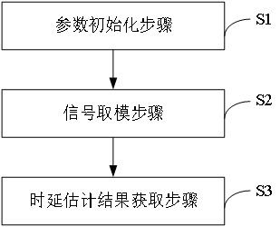
The present application relates to the field of signal processing, and in particular to a shortwave delay estimation method, system, computer equipment and readable storage medium, wherein the shortwave delay estimation method includes: a parameter initialization step, initializing the initial parameters of the filter, the initial Parameters include: weight coefficient vector W, number of iterations k max and convergence factor μ ;Signal modulo step to obtain the received two-shortwave multipath signal y 1 , y 2 , for two of the shortwave multipath signals y 1 , y 2 After the modulo is taken, the mean square error is obtained; in the step of obtaining the delay estimation result, the weight coefficient vector is iteratively updated based on the principle of minimizing the mean square error, so as to obtain the delay estimation result. Through the present application, the interference of the channel gain function to the signal is overcome, and a more accurate estimation of the relative time delay of the short-wave signal is achieved.

Description

technical field [0001] The present application relates to the field of signal processing, and in particular, to a shortwave delay estimation method, system, computer device and readable storage medium. Background technique [0002] The time delay estimation algorithm is the key research content in the field of signal processing, and it is also the premise for the realization of shortwave time difference-of-arrival positioning technology. [0003] Most of the traditional delay estimation algorithms are based on the dual-element signal processing model. The research focuses on the narrowband signal delay estimation algorithm, the multipath delay estimation algorithm and the delay estimation algorithm in the non-Gaussian noise environment. The problem is how to improve the accuracy of delay estimation and reduce the complexity of the algorithm under complex additive interference noise. However, in the time delay estimation of shortwave signals, since the signal will have sever...

Claims


Application Information

Patent Timeline
Patent Type & Authority Patents(China)
IPC IPC(8): H04B17/30H04B17/391
CPCH04B17/30H04B17/3912
Inventor 殷昊徐晓彤
Owner OCEAN UNIV OF CHINA
Why Eureka
Try Eureka