Direct insertion type heat dissipation LED light-emitting tube and installation method thereof

An LED light-emitting tube, in-line technology, applied in the direction of semiconductor devices, electrical components, circuits, etc., can solve the problems of damage to the LED light-emitting tube, damage to the LED light-emitting tube, short circuit, etc., to ensure the use effect, reduce the difficulty of installation, The effect of reducing poor contact

Pending Publication Date: 2022-06-24
湖北协进半导体科技有限公司
View PDF1 Cites 1 Cited by
  • Summary
  • Abstract
  • Description
  • Claims
  • Application Information

AI Technical Summary

Problems solved by technology

[0005] In order to overcome the above-mentioned defects of the prior art, the present invention provides an in-line heat-dissipating LED luminous tube and its installation method. After the installation is completed, connect it through the line that comes with the installation component. However, the insertion process of the LED light-emitting tube is relatively cumbersome. After the insertion is completed, it needs to be connected through an external connection structure. If there is instability in the connection part of the luminous tube, it will easily cause a short circuit or even damage the LED luminous tube, resulting in damage to the LED luminous tube and affecting the use of the LED luminous tube.

Method used


Image

  • Direct insertion type heat dissipation LED light-emitting tube and installation method thereof
  • Direct insertion type heat dissipation LED light-emitting tube and installation method thereof
  • Direct insertion type heat dissipation LED light-emitting tube and installation method thereof

Examples


Embodiment Construction

[0028] The technical solutions in the embodiments of the present invention will be clearly and completely described below with reference to the accompanying drawings in the embodiments of the present invention. Obviously, the described embodiments are only a part of the embodiments of the present invention, but not all of the embodiments. Based on the embodiments of the present invention, all other embodiments obtained by those of ordinary skill in the art without creative efforts shall fall within the protection scope of the present invention.

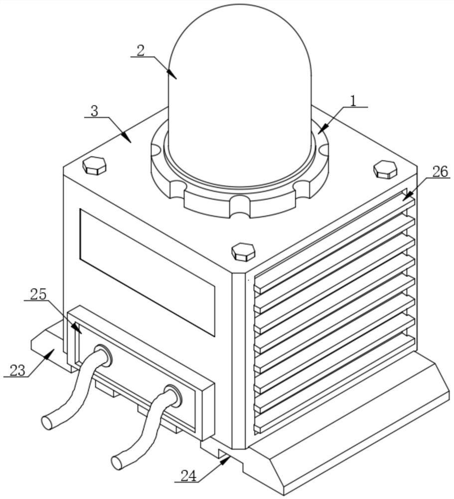
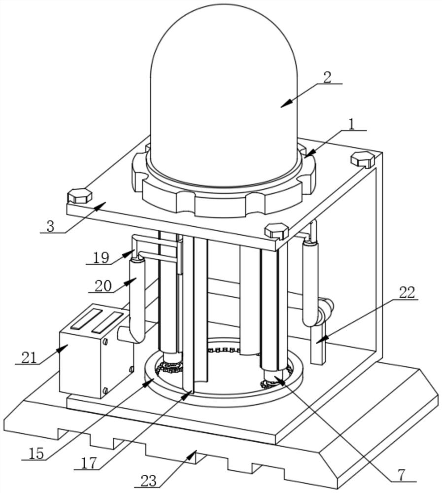
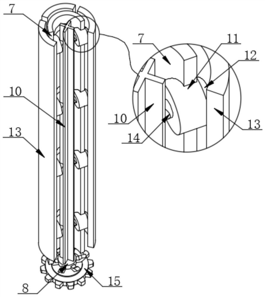
[0029] like Figure 1-6 As shown, the present invention provides an in-line heat dissipation LED light-emitting tube, comprising a fixed lamp holder 1, the upper surface of the fixed lamp holder 1 is provided with a glass protective cover 2, the fixed lamp holder 1 is located above the conversion joint 3, and the conversion joint The upper surface of 3 is provided with a limit chute 4, the fixed lamp holder 1 is clamped in the limit chu...


PUM


Abstract

The invention discloses a direct insertion type heat dissipation LED light-emitting tube and an installation method thereof, and particularly relates to the technical field of LED light-emitting tubes, the direct insertion type heat dissipation LED light-emitting tube comprises a fixed lamp holder, a glass protective cover is arranged on the upper surface of the fixed lamp holder, the fixed lamp holder is located above an adapter substitute, a limiting sliding groove is formed in the upper surface of the adapter substitute, and the glass protective cover is arranged in the limiting sliding groove. And the fixed lamp holder is clamped in the limiting sliding groove. By arranging the fixed lamp holder, the limiting sliding groove, the light-emitting tube pin, the extrusion block, the supporting rod and the extrusion rod, the LED light-emitting tube can be installed in the actual installation process in the mode that the LED light-emitting tube is directly inserted and then rotated, compared with an existing LED light-emitting tube installation mode, the LED light-emitting tube is more stable, the stability of the fixed lamp holder in the installation process is guaranteed, and the service life of the LED light-emitting tube is prolonged. And the condition that the pins of the light-emitting tube are in poor contact with the second wiring board due to looseness is reduced, so that the condition that the LED light-emitting tube is short-circuited or even damaged due to unstable connection parts is not easy to occur, and the use effect of the LED light-emitting tube is guaranteed.

Description

technical field [0001] The present invention relates to the technical field of LED light-emitting tubes, and more particularly, the present invention relates to an in-line heat-dissipating LED light-emitting tube and an installation method thereof. Background technique [0002] LED light-emitting tube is a kind of light-emitting tube with LED chip as the core, which is usually divided into LED pin type and SMD type. [0003] Chinese patent document (CN113217891A) discloses an LED light-emitting tube with the function of adjusting color, and it is proposed in the specification that "light-emitting diode is referred to as LED, which is made of compounds containing gallium, arsenic, phosphorus, nitrogen, etc. When the holes are recombined, it can radiate visible light, so it can be used to make light-emitting diodes, used as indicator lights in circuits and instruments, or to form text or digital displays, gallium arsenide diodes emit red light, gallium phosphide diodes emit gr...

Claims


Application Information

Patent Timeline
Patent Type & Authority Applications(China)
IPC IPC(8): H01L33/48H01L33/62H01L33/64
CPCH01L33/483H01L33/62H01L33/64
Inventor 李涛冯俊陈君陈强
Owner 湖北协进半导体科技有限公司
Why Eureka
Try Eureka