
Testing equipment for radio frequency chip

A technology of radio frequency chips and testing equipment, applied in the direction of electronic circuit testing, measuring electricity, measuring devices, etc., can solve the problems of damaged probes and radio frequency chips, poor contact between probes and pins, etc., to avoid waste and increase service life Effect

Active Publication Date: 2022-06-24
南京燧锐科技有限公司
View PDF8 Cites 2 Cited by
  • Summary
  • Abstract
  • Description
  • Claims
  • Application Information

AI Technical Summary

Problems solved by technology

[0005] This application provides a test device for radio frequency chips, which is used to solve the problem of poor contact between the probe and the pin due to too little pressure or damage to the probe due to too much pressure when manually controlling the movement of the probe. Needle and RF Chip Issues

Method used


Image

  • Testing equipment for radio frequency chip
  • Testing equipment for radio frequency chip
  • Testing equipment for radio frequency chip

Examples


Embodiment Construction

[0043] In order to make the objectives, technical solutions and advantages of the embodiments of the present application more clear, the embodiments of the present application will be further described in detail below with reference to the accompanying drawings.

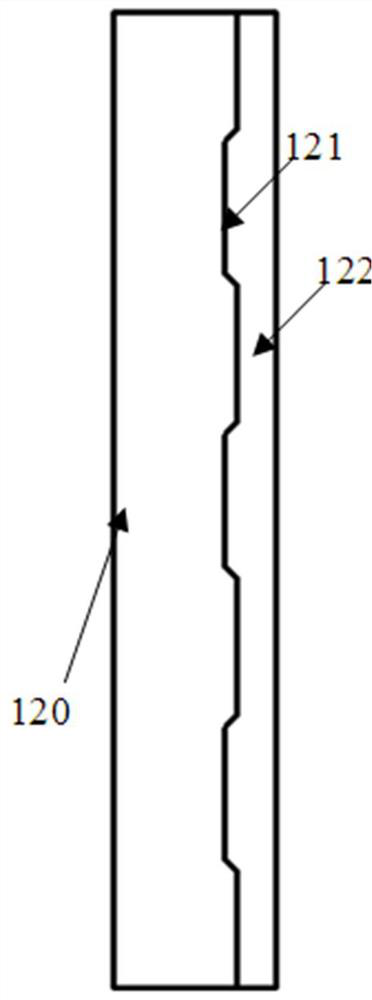
[0044] Please refer to figure 1 , which shows a structural diagram of a testing device for a radio frequency chip provided by an embodiment of the present application. The testing equipment may include: an opposite first pallet 110 , a second pallet 120 and a control unit (not shown in the figure).

[0045] Wherein, the first pallet 110 and the second pallet 120 may be parallel to each other. When the test equipment is placed horizontally, the first pallet 110 may be located above the second pallet 120, then the first pallet 110 may be referred to as an upper pallet, and the second pallet 120 may be referred to as a lower pallet; or , the first supporting plate 110 may be located below the second supporting plate 1...


PUM


Abstract

The invention discloses testing equipment for a radio frequency chip, and belongs to the field of chip testing. A probe and at least two pressure sensors are arranged on a first surface, opposite to a second supporting plate, in a first supporting plate of the test equipment; a second surface, opposite to the first supporting plate, of the second supporting plate is provided with a chip groove used for placing a radio frequency chip, a pin of the radio frequency chip is opposite to the probe, and the pressure sensor is used for measuring a pressure value between the probe and the pin; when the probe makes contact with the pin for the first time and the pressure values measured by the at least two pressure sensors are equal, the probe is controlled to be away from the pin; when the probe makes contact with the pin for the second time and the pressure value reaches a target pressure value, the radio frequency chip is tested through the probe, and the target pressure value is the pressure value when the radio frequency chip can be tested and the probe and the radio frequency chip are not damaged. According to the invention, waste of human resources can be avoided, the probe and the radio frequency chip can be protected while the radio frequency chip is normally tested, and the service life of the test equipment and the radio frequency chip is prolonged.

Description

technical field [0001] The present application relates to the field of chip testing, and in particular, to a testing device for radio frequency chips. Background technique [0002] Due to the small size of the radio frequency chip and the complicated manufacturing process, it may produce a faulty radio frequency chip. Therefore, before the radio frequency chip is put into use, it is usually necessary to test the radio frequency chip to ensure the quality of the radio frequency chip. [0003] In the related art, testing equipment is usually used to test the radio frequency chip. During the test, the RF chip can be placed face up in the test cavity in the test equipment, and then the probes in the test equipment can be manually controlled to move from bottom to top, so that the probes are in close contact with the pins in the RF chip, and finally The RF chip is tested by the probe. [0004] When the contact between the probe and the pin is manually controlled, if the pressur...

Claims


Application Information

Patent Timeline
Patent Type & Authority Applications(China)
IPC IPC(8): G01R31/28G01R1/02G01R1/04
CPCG01R31/2851G01R1/02G01R1/0408
Inventor 周健祖昀樵陆建华
Owner 南京燧锐科技有限公司
Learn More