
Ring main unit equipment state monitoring and fault diagnosis method

A technology for fault diagnosis and equipment status, which is applied in the direction of fault detection, fault location, and electrical measurement according to conductor type. Speed ​​of Learning and Computation, Increased Accuracy, Effect of Increased Prediction Rate

Active Publication Date: 2022-06-24
HUBEI TOP ELECTRIC POWER
View PDF14 Cites 0 Cited by
  • Summary
  • Abstract
  • Description
  • Claims
  • Application Information

AI Technical Summary

Problems solved by technology

[0002] In recent years, my country has continuously increased investment in distribution network construction, urban distribution network has developed rapidly, and the quality of power supply has been significantly improved. The ring main unit has been widely used due to its simple structure and flexible installation methods. There are a large number of cabinets scattered outdoors, and maintenance is difficult. The status monitoring and operation and maintenance inspection of primary equipment are under great pressure. With the increasing requirements for the operation and maintenance of ring network cabinets, the traditional inspection work mainly relies on manual inspections For inspection, operation and maintenance personnel use infrared thermometers, partial discharge detectors, sulfur hexafluoride pressure gauges and other equipment to conduct on-site inspections to evaluate the operating status of the ring network cabinet. Long-term operation in a defective state will eventually lead to power outages

Method used


Image

  • Ring main unit equipment state monitoring and fault diagnosis method
  • Ring main unit equipment state monitoring and fault diagnosis method
  • Ring main unit equipment state monitoring and fault diagnosis method

Examples


Embodiment Construction

[0041] The following specific embodiments are used to illustrate the embodiments of the present invention. Those who are familiar with the technology can easily understand other advantages and effects of the present invention from the contents disclosed in this specification. Obviously, the described embodiments are part of the present invention. , not all examples. Based on the embodiments of the present invention, all other embodiments obtained by those of ordinary skill in the art without creative efforts shall fall within the protection scope of the present invention.

[0042] Terms indicating a direction or positional relationship such as "inside" are based on the direction or positional relationship shown in the drawings, which are only for the convenience of description, and do not indicate or imply that a device or element must have a specific orientation, be configured in a specific orientation and operation, and therefore should not be construed as limiting the prese...


PUM


Abstract

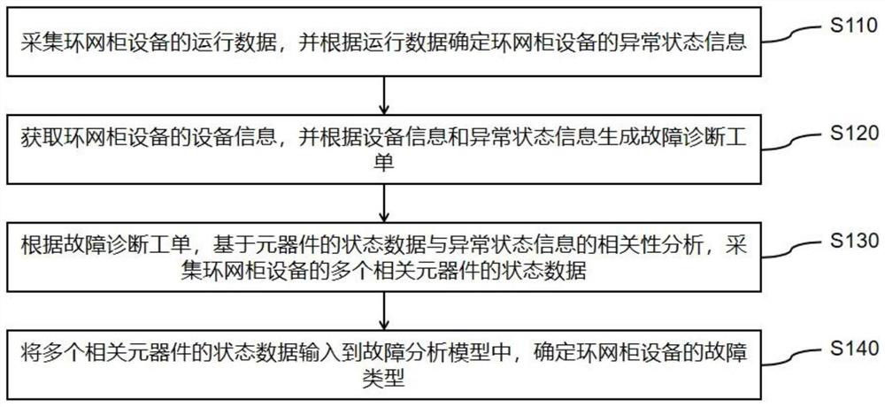
The invention discloses a ring main unit equipment state monitoring and fault diagnosis method, which comprises the following steps of: 1, acquiring operation data of ring main unit equipment, and determining abnormal state information of the ring main unit equipment according to the operation data; 2, acquiring equipment information of the ring main unit equipment, and generating a fault diagnosis work order according to the equipment information and the abnormal state information; step 3, according to the fault diagnosis work order, based on correlation analysis of the state data of the components and the abnormal state information, collecting state data of a plurality of related components of the ring main unit equipment; and 4, inputting the state data of the plurality of related components into the fault analysis model, and determining the fault type of the ring main unit equipment. According to the invention, the operation data of the ring main unit equipment is collected, the abnormal information of the equipment is found in time, the fault diagnosis work order is generated, the fault analysis model is used, the fault type is rapidly determined, real-time detection is realized, manual inspection is not needed, and prior information is provided for maintenance of equipment operation and maintenance personnel.

Description

technical field [0001] The invention relates to the technical field of power equipment monitoring and maintenance, in particular to a state monitoring and fault diagnosis method for ring network cabinet equipment. Background technique [0002] In recent years, my country has continuously increased investment in distribution network construction, urban distribution networks have developed rapidly, and the quality of power supply has been significantly improved. Ring network cabinets have been widely used due to their simple structure and flexible installation methods. The number of cabinets is large and scattered outdoors, which is difficult to maintain. The state monitoring and operation and maintenance inspection of primary equipment are under great pressure. With the increasing requirements for operation and maintenance of ring network cabinets, the traditional inspection work mainly relies on manual regular inspections. For inspection, the operation and maintenance personne...

Claims


Application Information

Patent Timeline
Patent Type & Authority Applications(China)
IPC IPC(8): G01R31/08G06N3/063G06N3/04
CPCG01R31/086G01R31/088G06N3/065G06N3/045
Inventor 黄涛朱志龙曾朕
Owner HUBEI TOP ELECTRIC POWER
Learn More