Automatic lifting device

An automatic lifting and lifting mechanism technology, which is applied in the direction of hoisting device, winch device, loading/unloading, etc., can solve the problems of difficult targeted design, complex structure, limited application, etc. Tight function, guarantee the effect of safety and stability

Active Publication Date: 2022-06-24
HARBIN INST OF TECH
View PDF6 Cites 0 Cited by
  • Summary
  • Abstract
  • Description
  • Claims
  • Application Information

AI Technical Summary

Problems solved by technology

[0003] In the research on the existing lifting device design, the scissor lift mechanism is mostly used to realize the lifting and transfer of goods. Although the structure of the scissor mechanism is simple and the design difficulty is relatively low, it can only ensure the movement of the goods in a single direction, which leads to Limited applications in tight installation spaces
Another form of lifting mechanism that is more frequently used is hoisting and hoisting, but the hoisting device body has a large structure and can only maintain a vertical movement in a single direction, so the applicability is not strong
There are also researchers who use link mechanisms to realize cargo lifting, but the existing link lifting mechanisms are complex in structure and large in size, and it is difficult to carry out targeted design according to the established trajectory
[0004] These principle designs not only directly affect the transfer performance of the lifting mechanism, but also indirectly limit the functional design and performance optimization of other parts of the overall equipment

Method used


Image

  • Automatic lifting device
  • Automatic lifting device
  • Automatic lifting device

Examples


Embodiment Construction

[0043] In order to make the technical solutions and advantages of the present application clearer, the present application will be described in detail below with reference to the accompanying drawings and specific embodiments.

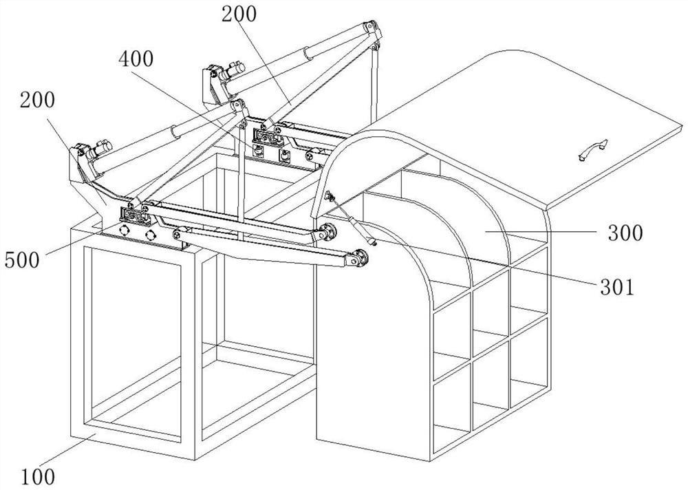
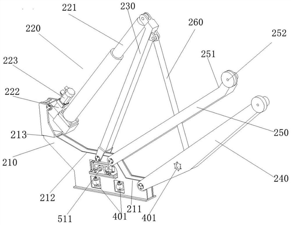
[0044] like Figure 1-2 As shown, an automatic lifting device of the present invention includes a base 100 , two sets of multi-link lifting mechanisms 200 and a warehouse 300 , wherein the two sets of multi-link lifting mechanisms 200 are respectively connected to both sides of the warehouse 300 , the multi-link lifting mechanism 200 includes:

[0045] a fixing seat 210, the fixing seat 210 is fixedly connected with the base 100;

[0046] a linear drive mechanism 220, one end of the linear drive mechanism 220 is hinged on the fixed seat 210;

[0047] a rocker 230, one end of the rocker 230 is hinged with the other end of the linear drive mechanism 220, and the other end of the rocker 230 is hinged with the fixing seat 210;

[0048] The main rod 240,...


PUM


Abstract

The invention relates to an automatic lifting device which comprises a base, two sets of multi-connecting-rod lifting mechanisms and a warehouse, the two sets of multi-connecting-rod lifting mechanisms are connected to the two sides of the warehouse respectively, and each multi-connecting-rod lifting mechanism comprises a fixing base fixedly connected with the base; one end of the linear driving mechanism is hinged to the fixed seat; one end of the rocker is hinged to the other end of the linear driving mechanism, and the other end of the rocker is hinged to the fixed seat; one end of the main rod is hinged to the fixing base, and the other end of the main rod is hinged to the side face of the warehouse. One end of the balance rod is hinged to the fixing base, the other end of the balance rod is hinged to the side face of the warehouse, and the balance rod and the main rod jointly form a parallelogram mechanism; one end of the pull rod is hinged to the rocker, and the other end of the pull rod is hinged to a certain position in the middle of the main rod; wherein the rocking bar, the balance bar, the main bar and the hinge point of the fixed seat are sequentially arranged from near to far.

Description

technical field [0001] The invention belongs to the field of transmission devices, in particular to an automatic lifting device. Background technique [0002] The cargo lifting device is a mechanical transmission device designed to improve the efficiency of cargo loading and unloading and improve the loading and unloading conditions. It is widely used in military warfare and civil life. Designing a reasonable, efficient and reliable cargo lifting device is the key to higher work efficiency. For example, in the battlefield environment, it is possible to rely on transportation equipment and use automatic cargo lifting devices for the transfer of weapons and rescue equipment, which can greatly reduce the input of labor costs and improve the wartime support capability; The use of automatic cargo lifting device can effectively improve work efficiency and maximize economic benefits. [0003] In the existing research on the design of lifting devices, scissors lifting mechanism is...

Claims


Application Information

Patent Timeline
Patent Type & Authority Applications(China)
IPC IPC(8): B66F19/00B65G65/30
CPCB66F19/00B65G65/30
Inventor 彭高亮刘世伟薛渊林鸿钊陈宏钧孙瑜韩逍
Owner HARBIN INST OF TECH
Why Eureka
Try Eureka