
A drive motor braking mechanism for cnc machining center

A brake mechanism and drive motor technology, which is applied to metal processing machinery parts, drive devices, metal processing equipment, etc., can solve the problems of excessive processing of materials and failure to stop rotation in time, and achieve the effect of avoiding excessive processing of workpieces

Active Publication Date: 2022-08-09
SHENZHEN JUJIANG TECH CO LTD
View PDF0 Cites 0 Cited by
  • Summary
  • Abstract
  • Description
  • Claims
  • Application Information

AI Technical Summary

Problems solved by technology

[0004] Aiming at the deficiencies of the prior art, the present invention provides a driving motor braking mechanism for CNC machining centers, which solves the problem that the motor drives the workpiece to move or process the workpiece during the working process of the current CNC machining center. After the power is turned off, the motor will continue to rotate for a period of time due to the influence of rotational inertia, and cannot stop rotating in time. Continuous rotation will lead to excessive processing of materials

Method used


Image

  • A drive motor braking mechanism for cnc machining center
  • A drive motor braking mechanism for cnc machining center
  • A drive motor braking mechanism for cnc machining center

Examples


Embodiment

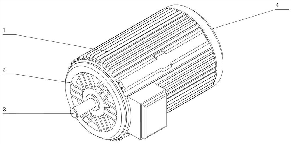
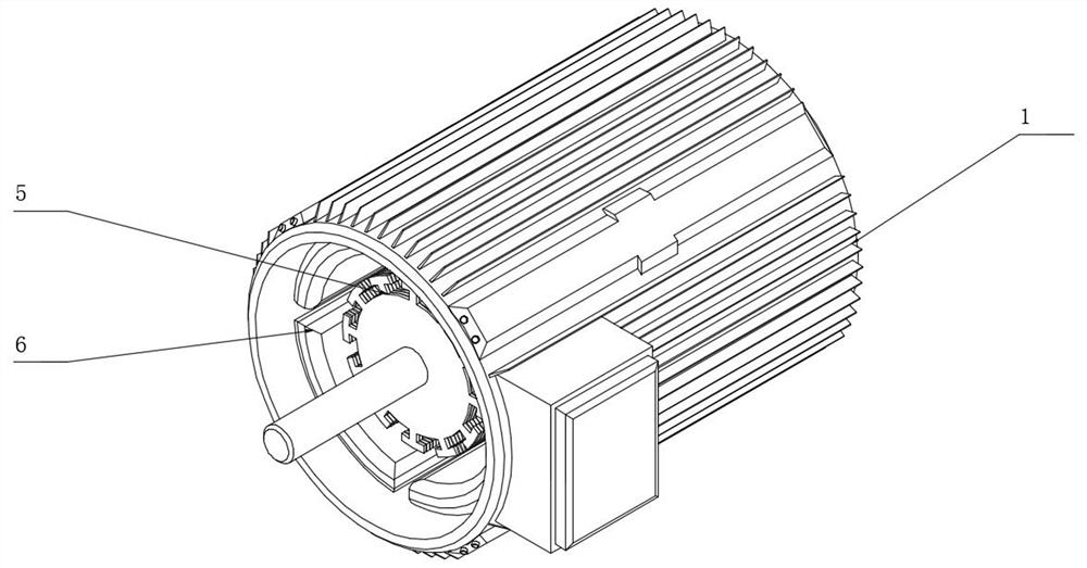
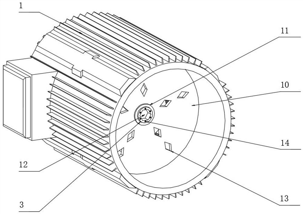
[0035] like figure 1 , 2, 3, 4, and 5, the embodiment of the present invention provides a drive motor braking mechanism for a CNC machining center, including a motor housing 1, and a stator 6 is fixedly installed inside the motor housing 1, and the stator 6 A rotor 5 is arranged inside the rotor 5, the rotor 5 is fixedly installed on the outer wall of the output shaft 3, and one end of the output shaft 3 is installed on the inner ring of the bearing 11, and the bearing 11 is fixedly installed at the center of the support plate 10, The support plate 10 is fixedly installed inside the motor housing 1, the other end of the output shaft 3 rotates through the front end cover 2 and extends to the outside of the front end cover 2, and the front end cover 2 is installed at one end of the motor housing 1, so the A rear end cover 4 is installed on the other end of the motor housing 1, and a driving device 7 is installed on the side surface of the rear end cover 4 close to the motor hou...


PUM


Abstract

The invention provides a driving motor braking mechanism for CNC machining centers, which relates to the technical field of motor braking, and includes a motor casing, a stator is fixedly installed inside the motor casing, a rotor is arranged inside the stator, and the The rotor is fixedly installed on the outer wall of the output shaft, one end of the output shaft is installed on the inner ring of the bearing, the bearing is fixedly installed at the center of the support plate, and the support plate is fixedly installed inside the motor casing, through the return spring The elasticity can push the moving sealing plate to move and reset, and push the support rod to move and reset through the guide slider, so that the support rod pushes the mounting seat and the two semicircular speed reduction plates to move, so that the connecting grooves set on one side of the two semicircular speed reduction plates are connected to the The surface of the brake disc can decelerate the brake disc, so that the motor can brake quickly after the power is cut off, so as to avoid the phenomenon of excessive machining of the workpiece caused by the continuous rotation of the motor after the power is cut off.

Description

technical field [0001] The invention relates to the technical field of motor braking, in particular to a driving motor braking mechanism for a CNC machining center. Background technique [0002] The CNC machining center is the CNC machining center, which is developed from the CNC milling machine. It is mainly used to process the workpiece. The CNC machining center needs to be driven by multiple drive motors during the working process, so that the CNC machining center can work normally. [0003] During the working process of the CNC machining center, the workpiece is often driven by the motor to move or process the workpiece, and the motor will continue to rotate for a period of time due to the influence of the rotational inertia after the power is turned off, and the rotation cannot be stopped in time. Continuous rotation will lead to excessive processing of materials. , so we make improvements and propose a drive motor braking mechanism for CNC machining centers. SUMMARY ...

Claims


Application Information

Patent Timeline
Patent Type & Authority Patents(China)
IPC IPC(8): B23Q5/20B23Q11/12
CPCB23Q5/20B23Q11/127Y02P70/10
Inventor 江喜允黄小四赖国平
Owner SHENZHEN JUJIANG TECH CO LTD
Learn More