
Conveying and cleaning machine for automobile part machining

A technology for auto parts and washing machines, which is applied in the direction of using liquid cleaning methods, cleaning methods and utensils, chemical instruments and methods, etc., which can solve the problems of limited cleaning effect of flushing devices, achieve good cleaning effect, improve cleaning effect, Guaranteed cleaning effect

Active Publication Date: 2022-06-24
南通艺能达精密制造科技有限公司
View PDF15 Cites 1 Cited by
  • Summary
  • Abstract
  • Description
  • Claims
  • Application Information

AI Technical Summary

Problems solved by technology

[0003] The purpose of the present invention is to provide a transmission cleaning machine for auto parts processing that can effectively improve the cleaning effect for the problem of limited cleaning effect of most traditional parts washing devices

Method used


Image

  • Conveying and cleaning machine for automobile part machining
  • Conveying and cleaning machine for automobile part machining
  • Conveying and cleaning machine for automobile part machining

Examples


Embodiment Construction

[0026] The following examples are for illustrative purposes only and are not intended to limit the scope of the invention.

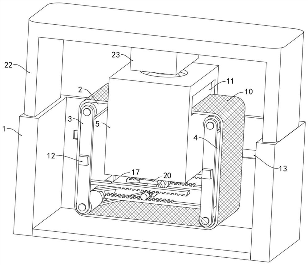
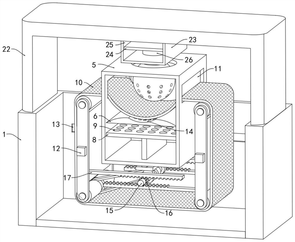
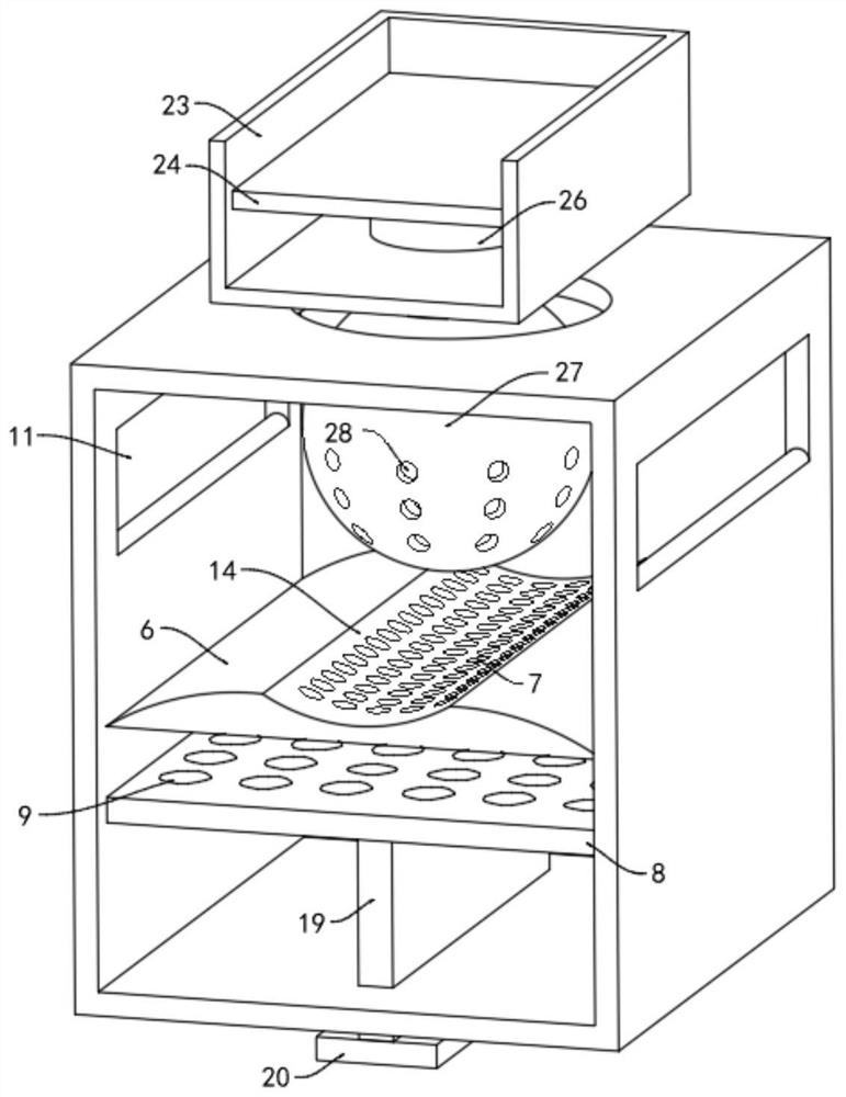
[0027] like Figure 1-5 As shown in the figure, a conveyor cleaning machine for processing automobile parts includes a frame body 1 with an open upper end, and two pairs of rotating rollers 2 arranged horizontally are arranged in the frame body 1, and each pair of rotating rollers 2 are located in the same vertical In the plane, the ends of each pair of rotating rollers 2 close to each other are provided with connecting plates 3 , and the rotating rollers 2 are rotatably connected with the connecting plates 3 .

[0028] It should be noted that, the outer side wall of each connecting plate 3 is fixedly connected to the limit block 12, the inner side wall of the frame body 1 is provided with a transverse groove 13 matched with the limit block 12, and the limit block 12 is slidably connected with the transverse groove 13. The entire frame can only be moved...


PUM


Abstract

The invention belongs to the field of automobile part cleaning, and particularly relates to a conveying cleaning machine for automobile part machining, which comprises a frame body with an opening at the upper end, two pairs of horizontally arranged rotating rollers are arranged in the frame body, and each pair of rotating rollers are positioned in the same vertical plane; connecting plates are arranged at the ends, close to each other, of each pair of rotating rollers, the rotating rollers are rotationally connected with the connecting plates, a vertical plate is fixedly connected between each pair of connecting plates, and a lower cleaning mechanism is arranged in the frame body; the lower cleaning mechanism comprises a cleaning box fixedly connected into the frame body, the cleaning box is arranged between the two pairs of rotating rollers, and a horizontally-arranged flushing plate is fixedly connected into the cleaning box. By arranging the lower cleaning mechanism, when a part located on the conveying belt is conveyed to a flushing plate and a lifting plate moves upwards, cleaning liquid below the flushing plate can be flushed to the position below the part through a plurality of lower flushing holes, the position below the part is fully flushed, and the cleaning effect is good.

Description

technical field [0001] The invention belongs to the field of automobile parts cleaning, in particular to a conveying cleaning machine for automobile parts processing. Background technique [0002] Debris and dust will remain on the surface of automobile parts after punching or engraving. Generally, they will be cleaned through the cleaning process. Most of the traditional cleaning methods are to place the parts on a conveyor belt that moves at a constant speed, and then pass through the top of the conveyor belt. However, this method can only clean the upper part of the part, and it is difficult to clean the entire part effectively. Other traditional cleaning methods are manually rinsed one by one, which has low cleaning efficiency and high labor intensity. big. SUMMARY OF THE INVENTION [0003] The purpose of the present invention is to solve the problem of limited cleaning effect of most traditional parts washing devices, and to provide a conveyor cleaning machine for au...

Claims


Application Information

Patent Timeline
Patent Type & Authority Applications(China)
IPC IPC(8): B08B3/02
CPCB08B3/022B08B2203/0217Y02W30/62
Inventor 王张兵
Owner 南通艺能达精密制造科技有限公司
Learn More