
Biomass fuel forming and granulating device

A biomass fuel and granulation device technology, applied in the direction of waste fuel, fuel, solid fuel, etc., can solve the problems of reducing the quality of biomass fuel, inability to stir, poor crushing effect of biomass raw materials, etc., to improve efficiency and effect, The effect of improving the degree of uniformity

Pending Publication Date: 2022-06-24
杨婷婷
View PDF1 Cites 2 Cited by
  • Summary
  • Abstract
  • Description
  • Claims
  • Application Information

AI Technical Summary

Problems solved by technology

[0004] However, when the above-mentioned prior art is used to produce biomass fuel, it cannot be stirred during the pulverization process of the biomass raw material, and the process of pulverizing the biomass raw material is relatively simple, resulting in relatively low crushing effect on the biomass raw material. Difference;
[0005] Moreover, the whole process of manufacturing biomass fuel does not have a mechanism for stirring biomass raw materials. If multiple biomass raw materials are used for production, the biomass raw materials that cannot be stirred evenly will affect their subsequent granulation effect. Thereby reducing the quality of biomass fuel;
[0006] Further, when it blows and dries the biomass raw materials, it can only blow at fixed points, and the biomass raw materials fall freely in the feeding pipe, so that the biomass raw materials on the lower side block the air duct, and the biomass raw materials on the upper side cannot be blown. The raw material is blown and dried, which reduces its drying effect on the biomass raw material

Method used


Image

  • Biomass fuel forming and granulating device
  • Biomass fuel forming and granulating device
  • Biomass fuel forming and granulating device

Examples


Embodiment 1

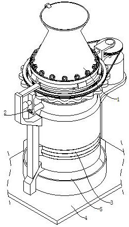
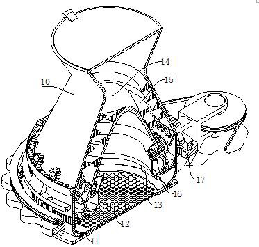
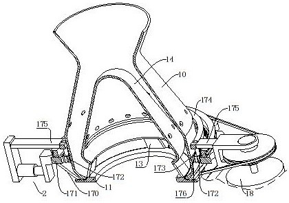
[0052] refer to figure 1 As shown, the biomass fuel molding and granulation device includes a pulverizing mechanism 1 for pulverizing and stirring biomass raw materials, and a drying mechanism 2 for stirring and drying biomass raw materials is provided on the lower side of the pulverizing mechanism 1, An extrusion granulation mechanism 3 is installed at the lower end of the drying mechanism 2, a base 4 is installed at the lower end of the extrusion granulation mechanism 3, and the upper end of the base 4 is located at the lower side of the discharge port of the extrusion granulation mechanism 3. Box 5.

[0053] Specifically, when the granulation production of biomass fuel is required, first, the biomass raw material to be pulverized is placed in the pulverizing mechanism 1, and the pulverizing mechanism 1 can pulverize the biomass raw material while stirring, thereby Increase the mixing uniformity of the biomass raw materials; then dry the biomass raw materials in the pulveri...

Embodiment 2

[0069] refer to Figure 7 As shown, on the basis of Embodiment 1, in order to improve the efficiency and effect of drying the raw materials, a drying mechanism 2 is provided; The reciprocating unit 20 is reciprocating. The lower end of the reciprocating unit 20 is installed with an exhaust duct 21 located on the lower side of the screening circular plate 12 and used to discharge hot air. The reciprocating unit 20 drives the exhaust duct 21 to perform reciprocating motion. The drying hood 22 is slidably arranged on the outer surface of the exhaust duct 21 and is rotatably connected with the support ring 11, and the drying hood 22 can be discharged from the exhaust duct 21. The hot air is limited; the drying cover 22 is provided with a stirring and discharging unit 23 for stirring and discharging the raw materials.

[0070] When the raw material needs to be dried, the exhaust pipe 21 is connected to the air outlet of the external hot air blower, and then the hot air blower can ...

Embodiment 3

[0078] refer to Figure 9 and Figure 10 As shown in the figure, on the basis of the second embodiment, in order to be able to extrude and granulate the pulverized and dried raw materials, an extrusion granulation mechanism 3 is set at the lower end of the drying mechanism 2; The granulation mechanism 3 includes a support leg 30, a support column 31, a ring frame 32, a discharge through hole 33, a motor cylinder 34, a supporting ring plate 35, a hole blocking and cutting unit 36, a granulating circular plate 37 and a granulating unit 38, The upper end of the base 4 is provided with a plurality of support legs 30 that will not interfere with the moving process of the material box 5, so as to facilitate the picking and placing of the material box 5; the support legs 30 and the limit connecting plate 200 and the motor plate 185 above them There are supporting columns 31 between them, and the supporting columns 31 can increase the stability of the limit connecting plate 200 and t...


PUM


Abstract

The invention relates to a biomass fuel forming granulation device which comprises a smashing mechanism used for smashing and stirring biomass raw materials, a drying mechanism used for stirring and drying the biomass raw materials is arranged on the lower side of the smashing mechanism, an extrusion granulation mechanism is installed at the lower end of the drying mechanism, and a base is installed at the lower end of the extrusion granulation mechanism. A material receiving box used for receiving materials is arranged at the upper end of the base and located on the lower side of a discharge port of the extrusion granulation mechanism; the biomass fuel particle production device can solve the following problems in the biomass fuel particle production process in the prior art: the biomass raw material crushing process is relatively simple, so that the biomass raw material crushing effect is relatively poor; no mechanism for stirring biomass raw materials is arranged in the whole process of manufacturing the biomass fuel; and only fixed-point air blowing can be performed, so that the biomass raw materials on the lower side easily block an air flue, the biomass raw materials on the upper side cannot be subjected to air blowing drying, and the drying effect on the biomass raw materials is reduced.

Description

technical field [0001] The invention relates to the field of biomass fuel production, in particular to a biomass fuel molding and granulation device. Background technique [0002] Biomass fuel refers to the burning of biomass materials as fuel, which is generally made of straw, straw, rice husk, peanut husk, corncob, camellia husk, cottonseed husk, etc. through crushing, mixing, extrusion, drying and other processes. Large rod, block or granular, it is a new type of clean fuel that can be used for direct combustion; its performance is better than wood, equivalent to medium bituminous coal, can be directly burned, and the combustion characteristics are significantly improved; at the same time, it has less black smoke and firepower. It has the advantages of prosperous, sufficient combustion, no fly ash, clean and hygienic, and it is easy to transport and store. It can replace coal directly in boilers for power generation or heat supply, and can also be used to solve basic livi...

Claims


Application Information

Patent Timeline
Patent Type & Authority Applications(China)
IPC IPC(8): B02C18/12B01J2/20B02C15/00B02C18/18B02C18/24B02C21/00B02C23/10B02C23/20C10L5/44F26B21/00
CPCB02C18/12B02C18/18B02C18/24B02C15/00B02C21/00B02C23/10B02C23/20B01J2/20C10L5/445F26B21/00F26B21/004C10L2290/08C10L2290/28C10L2290/30B02C2015/002Y02E50/30
Inventor 杨婷婷
Owner 杨婷婷
Learn More