Method for calculating frame collision rate of frame on CAN (Controller Area Network) bus and method for minimizing CAN bus resources
A technology of CAN bus and calculation method, applied in the field of data transmission, can solve the problems of inability to optimize bus resources, inability to calculate collision frame rate, etc., and achieve the effect of optimal configuration
Active Publication Date: 2022-06-21
SHENZHEN POWEROAK NEWENER
View PDF5 Cites 0 Cited by
- Summary
- Abstract
- Description
- Claims
- Application Information
AI Technical Summary
Problems solved by technology
[0006] The purpose of the present invention is to overcome the shortcomings of the prior art that the frame collision rate cannot be calculated, and then the bus resources cannot be optimized, and a method for calculating the frame collision rate of frames on the CAN bus and a method for minimizing CAN bus resources are provided
Method used
View moreImage
Smart ImageViewing Examples
Examples
Embodiment 1
Embodiment 2
Login to View More PUM
 Abstract
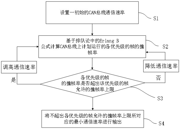
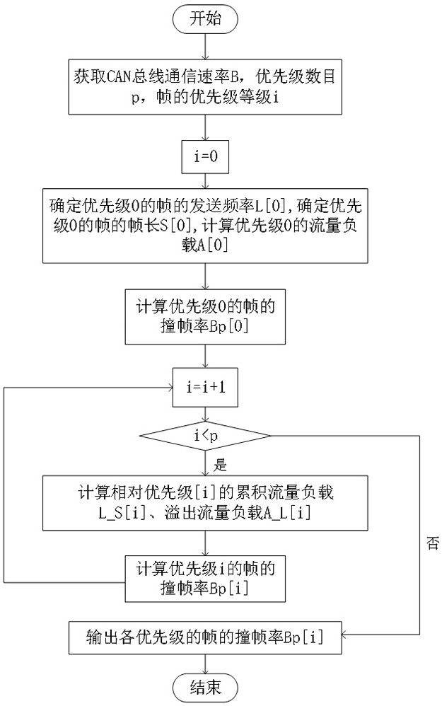
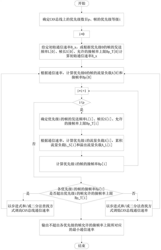
The invention provides a method for calculating a frame collision rate of a frame on a CAN bus and a method for minimizing CAN bus resources. The method for minimizing the CAN bus resources comprises the following steps: S1, setting an initial CAN bus communication rate; s2, calculating a frame collision rate of each priority frame planned to run on the CAN bus based on an Erlang B formula in a queuing theory at the preset rate of the step S1; s3, judging whether the frame collision rate, calculated in the step S2, of the frame of each priority exceeds the upper limit of the frame collision rate allowed by the frame of the priority or not; if yes, increasing the CAN bus communication rate in the step S1 and entering the step S2 to continue circulation; if not, lowering the CAN bus communication rate in the step S1 and entering the step S2 to continue circulation; and S4, outputting the minimum communication rate corresponding to the frame collision rate upper limit allowed by the frames not exceeding the priorities so as to complete optimization. The invention provides a set of frame collision rate algorithm, so that the required minimum bus resource is calculated according to the upper limit of the frame collision rate of each priority frame, and the resource is optimized.
Description
technical field [0001] The invention relates to the technical field of data transmission, in particular to a method for calculating the collision frame rate of frames on a CAN bus and a method for minimizing CAN bus resources. Background technique [0002] In the automobile industry, due to the requirements of safety, comfort, convenience, low power consumption, and low cost, various electronic control systems have been developed. Since the data types used for communication between these systems and the requirements for reliability are not the same, there are many cases composed of multiple buses, and the number of wiring harnesses also increases accordingly. In order to meet the needs of "reducing the number of wire harnesses" and "carrying out high-speed communication of a large amount of data through multiple LANs", in 1986, the German electric company Bosch developed the CAN communication protocol for automobiles. [0003] The full name of CAN is Controller Area Network...
Claims
Login to View More Application Information
Patent Timeline
 Patent Type & Authority Applications(China)
IPC IPC(8): H04L12/40H04L41/0823H04L43/0823
CPCH04L12/40169H04L43/0823H04L41/0823H04L2012/40215
Inventor 马辉雷健华郭志华李帆秦赓李海洋
Owner SHENZHEN POWEROAK NEWENER
Features
- R&D
- Intellectual Property
- Life Sciences
- Materials
- Tech Scout
- Unparalleled Data Quality
- Higher Quality Content
- 60% Fewer Hallucinations
Learn More Browse by: Latest US Patents, China's latest patents, Technical Efficacy Thesaurus, Application Domain, Technology Topic, Popular Technical Reports.
© 2025 PatSnap. All rights reserved.Legal|Privacy policy|Modern Slavery Act Transparency Statement|Sitemap|About US| Contact US: help@patsnap.com


