Straightening device for elevator guide rail
An elevator guide rail and straightening technology, which is applied to the feeding device, positioning device, storage device, etc., can solve the problems of poor calibration ability and inability to accurately position the elevator guide rail, and achieve the effect of facilitating calibration, enhancing practical performance, and preventing tilting.
- Summary
- Abstract
- Description
- Claims
- Application Information
AI Technical Summary
Problems solved by technology
Method used
Image
Examples
Embodiment 1
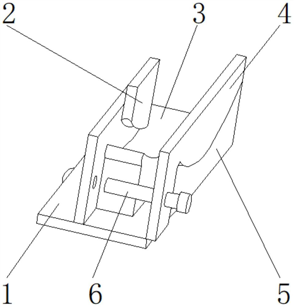
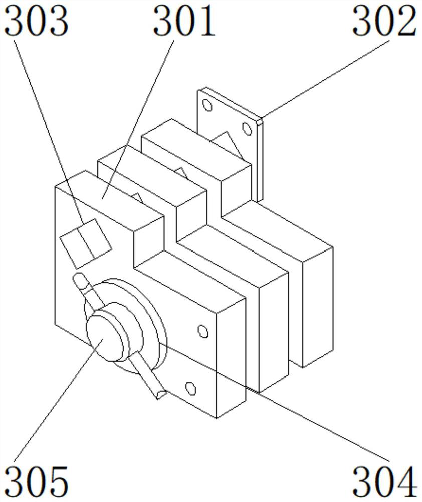
[0028] like Figure 1-5 As shown, the present invention provides a straightening device for elevator guide rails, comprising a main body 1, the upper end of the main body 1 is provided with a clamping plate 4, one side of the clamping plate 4 is provided with a placement groove 5, and the other side of the clamping plate 4 is provided with a connecting device 6. The rear end of the connecting device 6 is provided with a positioning mechanism 3, and the upper end of the positioning mechanism 3 is provided with a shock absorption and noise reduction device 2; Valve 305, the vertical alignment plate 302 is located on one side of the fixed plate 301, and the sliding block 303 is located on the other side of the fixed plate 301; A welding block is provided between the vertical alignment plates 302 , and the other side of the fixing plate 301 is fixedly connected to one side of the vertical alignment plate 302 through the welding block.
[0029] In this embodiment, the grooves form...
Embodiment 2
[0031] like Figure 1-5 As shown, on the basis of Embodiment 1, the present invention provides a technical solution: preferably, the rotating shaft 304 is located on one side of the outer surface of the fixed plate 301 , and the regulating valve 305 is located on one side of the rotating shaft 304 .
[0032] A threaded groove is provided between the regulating valve 305 and the rotating shaft 304. One side of the rotating shaft 304 is detachably connected to one side of the regulating valve 305 through the threaded groove. A notch is provided between the fixing plate 301 and the rotating shaft 304. The fixing plate One side outer surface of 301 is detachably connected with the other side of the rotating shaft 304 through the notch.
[0033] In this embodiment, the straightening ability of the device can be enhanced to make its calibration accuracy better. The rotating shaft 304 is rotated by the regulating valve 305 to adjust the spacing of the plurality of fixing plates 301 s...
Embodiment 3
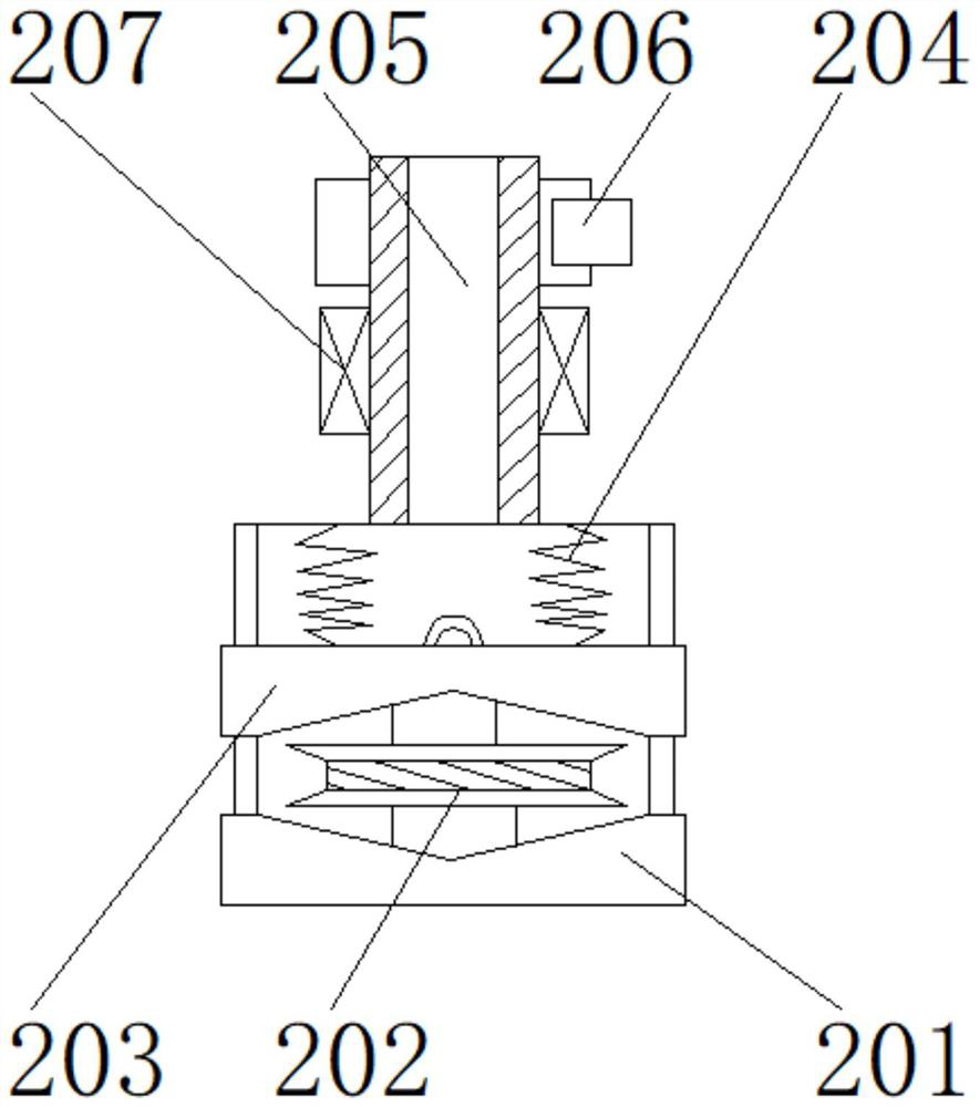
[0035] like Figure 1-5 As shown, on the basis of Embodiment 1, the present invention provides a technical solution: preferably, the shock absorption and noise reduction device 2 includes a fixed bottom plate 201, a shock absorber 202, a spiral steel 203, an elastic element 204, a muffler plate 205, The leveling steel plate 206, the load indicator 207, the shock absorber 202 is located at the upper end of the fixed bottom plate 201, the spiral steel 203 is located at the upper end of the shock absorber 202, the elastic element 204 is located at the upper end of the spiral steel 203, and the muffler plate 205 is located at the upper end of the elastic element 204. At the upper end, the leveling steel plate 206 is located on one side of the muffler plate 205 , and the load indicator 207 is located on the other side of the muffler plate 205 .
[0036] A screw is arranged between the shock absorber 202 and the fixed bottom plate 201, the upper end of the fixed bottom plate 201 is ...
PUM
 Abstract
Description
Claims
Application Information
 - R&D
- Intellectual Property
- Life Sciences
- Materials
- Tech Scout
- Unparalleled Data Quality
- Higher Quality Content
- 60% Fewer Hallucinations
Browse by: Latest US Patents, China's latest patents, Technical Efficacy Thesaurus, Application Domain, Technology Topic, Popular Technical Reports.
© 2025 PatSnap. All rights reserved.Legal|Privacy policy|Modern Slavery Act Transparency Statement|Sitemap|About US| Contact US: help@patsnap.com


