
Non-contact kinetic energy detection method based on vision measurement

A visual measurement and non-contact technology, applied in image analysis, image enhancement, instruments, etc., can solve the problems of difficult visual feature detection, calibration, and on-site measurement equipment layout, so as to increase the feasibility and ease of promotion, Avoid the influence of vibration, easy to build and efficient

Pending Publication Date: 2022-06-17
NANJING UNIV OF TECH
View PDF0 Cites 0 Cited by
  • Summary
  • Abstract
  • Description
  • Claims
  • Application Information

AI Technical Summary

Problems solved by technology

[0005] Purpose of the invention: the present invention provides a non-contact kinetic energy detection method based on visual measurement. The method utilizes the video collected on the spot and uses image processing technology and visual measurement algorithm to detect the kinetic energy of moving objects. It solves the problem of existing Low accuracy of visual measurement, high cost of equipment operation and maintenance, difficulty in arranging on-site measurement equipment, an

Method used


Image

  • Non-contact kinetic energy detection method based on vision measurement
  • Non-contact kinetic energy detection method based on vision measurement
  • Non-contact kinetic energy detection method based on vision measurement

Examples


Example Embodiment

[0059]实施例:将本发明的基于视觉测量的非接触式动能检测方法应用于某种运动车门的动能测量中,实时工作流程如下:

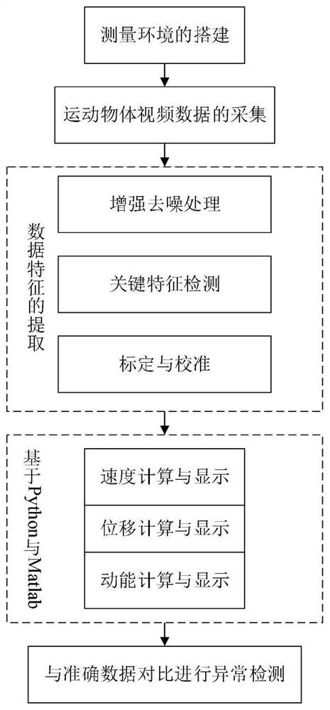
[0060]如图1所示,为本发明提供的实施基于视觉测量的非接触式动能检测方法的总体流程图,具体步骤包括:

[0061](1.1)测量环境的搭建;

[0062](1.2)视频数据的采集;

[0063](1.3)视频数据关键特征的提取;

[0064](1.4)基于Python与Matlab对位移、速度、动能进行计算与显示;

[0065](1.5)与准确数据对比进行异常检测。

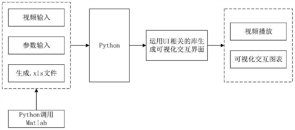
[0066]发明提供一种基于视觉测量的非接触式动能检测方法,只需搭建一个具有平行光源无振动与噪声的相对封闭的环境即可。视频的采集运用CCD相机拍摄整个门在一定时长的运动画面,采集过程中尽量保持背景简单且无振动。视频数据关键特征则需对相机进行标定以及提取镜头关键帧从而减少算法运算量,如门的颜色分明的边缘与门框等。利用Matlab处理数据能力强大以及Python具有丰富库的优势,运用Matlab编写对视频数据降噪与关键帧提取算法从而计算出车门的实际运动的位移、速度、动能,运用Python编写视频播放与读取.xls文件生成可视化图表算法,使用Python调用Matlab,使得程序功能更加全面与直观。

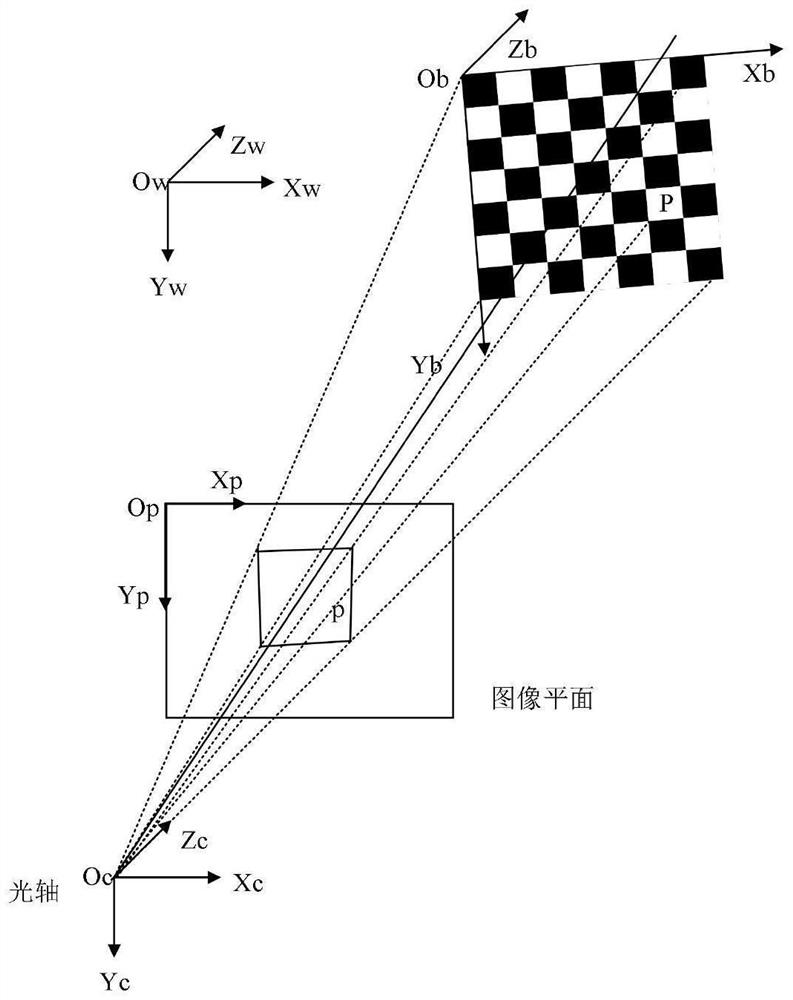
[0067]如图2所示,为相机标定示意图。

[0068]棋盘标定的步骤为:

[0069](1)打印一张棋盘格,把它贴在一个平面上,作为标定物。

[0070](2)通过调整标定物或摄像机的方向,为标定物拍摄一些不同方向的照

[0071](3)从照片中提取棋盘格角点。

[0072](4)估算理想无畸变的情况下,五个内参和六个外参。

[0073](5)应用最小二乘法估算实际存在径向畸变下的畸变系数。

[0074](6)极大似然法,优化估计,提升估计精度。

[0075]在相机参数标定中,世界坐标系是客观三维世界的绝对坐标,相机坐标系是以相机为原点,相机的光轴为轴,像平面坐标系与相机坐标系对应平行,像平面原点与相机坐标系原点之间的距离就是镜头的焦距。

[0076]设(xc,yc)是图像中心的坐标。因此坐标系中任一点和其在图像坐标系中的对应点间的坐标变换关系为:

[0077]

[0078]

[0079]fNy、Ny / Nx均为相机的内部参数,令fNy=a、Ny / Nx=b。则

[0080]

[0081]

[0082]其中,D,α是外部参数,表示相机的...


PUM


Abstract

The invention discloses a non-contact kinetic energy detection method based on visual measurement. The non-contact kinetic energy detection method comprises the following steps: building a measurement environment; collecting video data; extracting key features of the video data; the displacement, the speed and the kinetic energy are calculated and displayed based on Python and Matlab; and comparing with accurate data to perform anomaly detection. The method mainly has the advantages of being high in precision and non-contact, the measurement efficiency is higher than that of a traditional measurement algorithm, and automatic measurement is easy to achieve.

Description


Claims


Application Information

Patent Timeline
IPC IPC(8): G06T7/246G06T7/00G06T7/13G06T7/80G06T5/00G06T5/20
CPCG06T7/246G06T7/0004G06T7/13G06T7/80G06T5/002G06T5/20G06T2207/10016G06T2207/20164
Inventor 吴泽缪小冬
Owner NANJING UNIV OF TECH
Learn More