Eureka AIR delivers breakthrough ideas for toughest innovation challenges, trusted by R&D personnel around the world.

Washing machine speed reduction clutch device, washing machine and control method of washing machine

A technology of clutch device and washing machine, which is applied to the control device of washing machine, washing device, other washing machines, etc., and can solve the problem that the miniaturization of automatic pulsator washing machine cannot meet the cost and installation space requirements, and the structure of deceleration clutch device is complex and affects Clothes cleaning ratio and other issues, to meet the cost and installation space requirements, occupy a small space, improve the effect of cleaning ratio

Pending Publication Date: 2022-06-17
ZHEJIANG SANXING MECHANICAL & ELECTRONICSAL STOCK
View PDF0 Cites 1 Cited by
  • Summary
  • Abstract
  • Description
  • Claims
  • Application Information

AI Technical Summary

Problems solved by technology

[0005] In order to solve the above problems, the present invention aims to solve the problem that the deceleration clutch device of the existing fully automatic pulsator washing machine cannot completely lock the inner tub during the washing process, which causes the inner tub to rotate during the washing process, which affects the washing ratio of clothes and increases energy consumption. ; and the existing deceleration clutch device has a complex structure, large volume, and high cost, which cannot meet the cost and installation space requirements of the existing fully automatic pulsator washing machine miniaturization. A deceleration clutch device for washing machine, washing machine and its control are proposed The method, specifically, adopts the following technical solutions:

Method used


Image

  • Washing machine speed reduction clutch device, washing machine and control method of washing machine
  • Washing machine speed reduction clutch device, washing machine and control method of washing machine
  • Washing machine speed reduction clutch device, washing machine and control method of washing machine

Examples


Embodiment Construction

[0053] In order to make the purposes, technical solutions and advantages of the embodiments of the present invention clearer, the technical solutions in the embodiments of the present invention will be clearly and completely described below with reference to the accompanying drawings. Obviously, the described embodiments are some, but not all, embodiments of the present invention.

[0054] Accordingly, the following detailed descriptions of embodiments of the present invention are not intended to limit the scope of the claimed invention, but merely represent some embodiments of the present invention. Based on the embodiments of the present invention, all other embodiments obtained by those of ordinary skill in the art without creative efforts shall fall within the protection scope of the present invention.

[0055] It should be noted that the embodiments of the present invention and the features and technical solutions of the embodiments may be combined with each other unless ...


PUM


Abstract

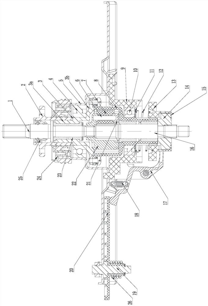
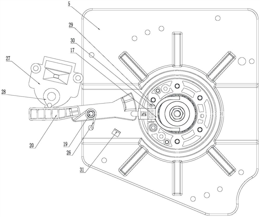
The invention discloses a speed reduction clutch device of a washing machine. The inner barrel shaft is rotatably arranged on the periphery of the impeller shaft in a sleeving manner; one end of the impeller shaft is in transmission connection with the speed reduction gear train; one end of the input shaft is in transmission connection with the speed reduction gear train; the input shaft sleeve is rotatably arranged on the periphery of the input shaft in a sleeving mode, and the inner barrel shaft is fixedly connected with the input shaft sleeve; the clutch sleeve is arranged on the input shaft sleeve in a sleeving mode in an axial sliding mode, and the clutch sleeve and the input shaft sleeve are matched in a limiting mode in the circumferential direction; the fixed disc is fixedly arranged above the clutch sleeve, and the clutch sleeve is arranged on the fixed disc; and the clutch sleeve is controlled to slide upwards to be meshed and fixed with the fixed disc so as to limit the circumferential rotation of the input shaft sleeve and the inner barrel shaft. According to the speed reduction clutch device of the washing machine, the inner barrel can be completely locked in the washing process, follow-up rotation of the inner barrel in the washing process is avoided, the washing ratio of clothes is increased, and energy consumption is reduced.

Description

technical field [0001] The invention relates to the technical field of laundry equipment, in particular to a deceleration clutch device for a washing machine, a washing machine and a control method thereof. Background technique [0002] A fully automatic pulsator washing machine, as a commonly used household appliance, generally includes an outer tub, an inner tub arranged inside the outer tub, and a pulsator arranged inside the inner tub. Wherein, the outer bucket is used as a water bucket for holding washing water, the inner bucket is used as a dehydration bucket, which can be driven to rotate at high speed for dehydration, and the pulsator can be driven in the inner bucket to rotate forward and reverse to stir the washing water to form washing. water flow, washing clothes. [0003] In the existing fully automatic pulsator washing machine, in order to prevent the inner tub from following the rotation to affect the washing ratio during the washing process, it is necessary ...

Claims


Application Information

Patent Timeline
Patent Type & Authority Applications(China)
IPC IPC(8): D06F37/30D06F33/30
CPCD06F37/30D06F33/30
Inventor 林华斌杨克坚陈昌昌蔡泽豪马定豪
Owner ZHEJIANG SANXING MECHANICAL & ELECTRONICSAL STOCK
Why Eureka
Eureka Blog
Learn More