


Quick Research
Generate reliable direction feasibility study reports for your R&D in just a few steps.

Technical Q&A
Discover and master advanced knowledge NOW. Basics, ideas, possibilities, all at once.

Find Solutions
As an expert in R&D theories, this can generate solutions to your technical problems instantly.

Evaluate Feasibility
Analyze your overall solution with one click, know your potential R&D risks in advance.

Monitor Landscape
Get weekly tech updates, stay abreast of the latest tech innovations and key insights.
Gate drive circuit
A gate drive circuit and power supply technology, which is applied in the direction of electronic switches, electrical components, output power conversion devices, etc., to achieve the effect of preventing through current
- Summary
- Abstract
- Description
- Claims
- Application Information
AI Technical Summary
Problems solved by technology
Method used
Image

Examples
Embodiment approach 1
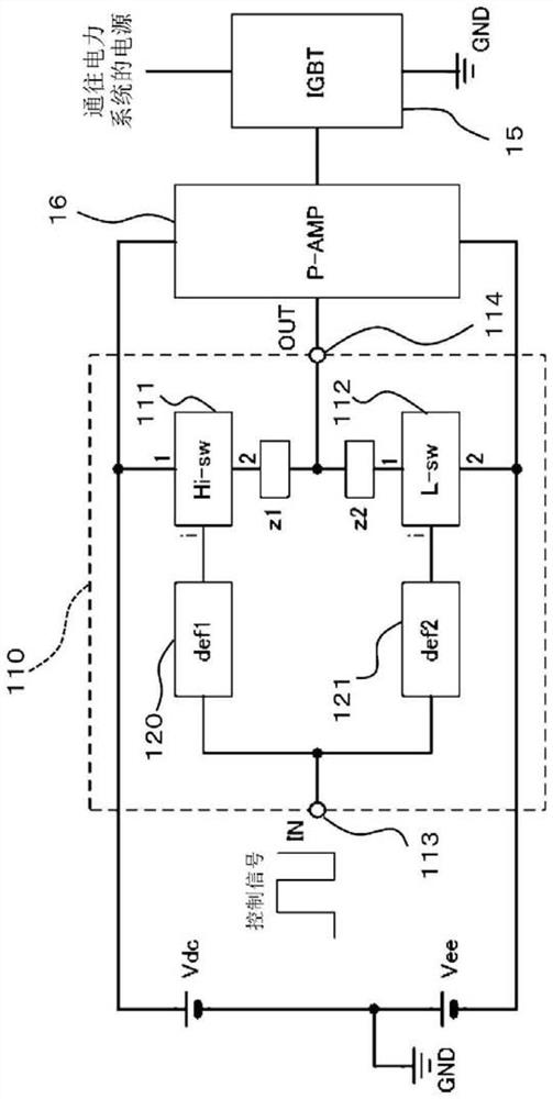
[0067] The present embodiment is a switching circuit used in a gate driving circuit that drives a power switch such as an IGBT or a MOSFET. figure 1 A circuit diagram of a gate drive circuit including the switching circuit 110 is shown in . This gate drive circuit is a gate drive circuit that drives the gate of IGBT15. Here, IGBT15 corresponds to a suitable example of the semiconductor switch of a claim. Moreover, the gate driving circuit mainly includes the switch circuit 110 and may include other circuits. For example, P-AMP16 may also be included (see figure 1 ), but may not be included depending on the application. Switching circuit 110 according to Embodiment 1 is characterized in that differential circuits 120 and 121 are connected to input terminals of high-side switch 111 and low-side switch 112 . These differentiating circuits 120, 121 produce the same effect as that of the case where the level shift circuit is inserted on the input side of the high-side switch ...
Embodiment approach 2
[0103] 2. Example using bipolar transistors in Embodiment 2
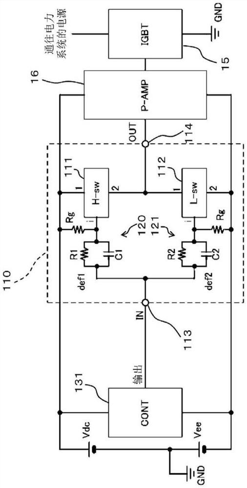
[0104] Figure 5 is a circuit block diagram of a gate drive circuit including the switch circuit 110 in which the high-side switch 111 a uses a pnp transistor and the low-side switch 112 a uses an npn transistor. Figure 5 In the gate driving circuit, the switch circuit 110 is also used as the main structure, but other structures may also be included. For example, the gate drive circuit may also include P-AMP16, but may not.
[0105] In the case of the use of so-called bipolar transistors, the same as explained heretofore figure 1 ~The circuit shown in Figure 3 has roughly the same effect. Also, for each switch of the high-side switch 111a, a transistor is used instead of a MOSFET, whereby various advantages can be produced.
[0106] Hereinafter, expressions related to the second embodiment in which transistors are used for the high-side switch 111 a and the low-side switch 112 a are added. The base-emitter ...
Embodiment approach 3
[0122] 3. Embodiment 3: Example using a Zener diode
[0123] Figure 6 It is a block diagram of a case where the Zener diode D1 is inserted into the output circuit of the switching circuit 110a. In a gate drive circuit that drives a power switch (IGBT15, etc.), the output of the switch circuit described in this embodiment and the gate drive circuit using the switch circuit is diversified. Figure 6 The gate drive circuit in 2000 has a switch circuit 110a as its main structure, but may also include other structures. For example, the gate drive circuit may or may not include P-AMP16.
[0124] For example, the output sometimes requires a swing from Vdc to Vee, and sometimes the voltage range must be limited like Vdc~GND. In this case, if Figure 6 As shown, by inserting a diode D1 between the transistor constituting the high-side switch 111 a or the low-side switch 112 a and the output terminal 114 , the swing of the output voltage can be adjusted.
[0125] For example, wh...
PUM
 Abstract
Description
Claims
Application Information
 - R&D Engineer
- R&D Manager
- IP Professional
- Industry Leading Data Capabilities
- Powerful AI technology
- Patent DNA Extraction
Browse by: Latest US Patents, China's latest patents, Technical Efficacy Thesaurus, Application Domain, Technology Topic, Popular Technical Reports.
© 2024 PatSnap. All rights reserved.Legal|Privacy policy|Modern Slavery Act Transparency Statement|Sitemap|About US| Contact US: help@patsnap.com