
Semiconductor thickness detection and comparison device

A technology of thickness detection and comparison device, which is applied in semiconductor/solid-state device testing/measurement, cleaning methods and utensils, chemical instruments and methods, etc., to achieve the effects of avoiding inaccurate detection results, improving work efficiency, and accurate detection results

Active Publication Date: 2022-06-10
浙江晶睿电子科技有限公司
View PDF7 Cites 4 Cited by
  • Summary
  • Abstract
  • Description
  • Claims
  • Application Information

AI Technical Summary

Problems solved by technology

[0003]Due to the fact that direct contact is not suitable for the detection of semiconductor sheets, the end faces of semiconductors are easily scratched or polluted, and conventional thickness detection devices cannot The thickness and flatness of semiconductors are conveniently and stably non-contact detection work, which cannot guarantee the stability and safety of semiconductor thickness detection work, and conventional detection devices cannot compare the same semiconductor in different directions at the same time during the working process detection work, so it needs to conduct multiple detections on the same semiconductor, and compare and analyze the results to avoid errors in the detection results, and conventional detection devices cannot perform convenient and stable detection of semiconductors of different sizes during the working process. Clamping and positioning, at the same time, cannot effectively avoid the warping phenomenon of the semiconductor during placement, and thus cannot guarantee the accuracy of subsequent detection results, low work efficiency and poor practicability, so it is necessary to provide a semiconductor thickness detection comparison device to meet user needs

Method used


Image

  • Semiconductor thickness detection and comparison device
  • Semiconductor thickness detection and comparison device
  • Semiconductor thickness detection and comparison device

Examples


Embodiment

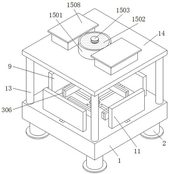
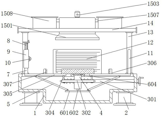
[0035] This ensures the stability of the bonding state of the connecting scraper rod 1506 on the filter screen plate 1502, thereby ensuring the automatic stability of the follow-up push and collection of dust and impurities, thereby ensuring the accuracy and safety of the follow-up detection work.

[0036] It should be noted that the present invention is a semiconductor thickness detection and comparison device. First, the staff can place the semiconductor that needs to be tested and compared on the workbench 1, and then the staff can rotate the worm 301. At this time, the worm 301 Under the action of rotation, the worm wheel 302 that is meshed and connected can be driven to rotate stably on the fixed pipe 4. At this time, during the rotation of the worm wheel 302, combined with the limit guide action of the limit plate 305, each guide groove 303 can drive the corresponding guide. The limiting plates 305 on the rod 304 move to the middle at the same time. At this time, under th...


PUM


Abstract

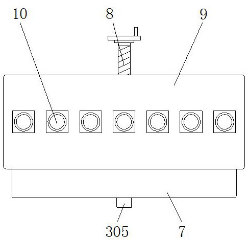
The invention belongs to the field of semiconductor detection, and particularly relates to a semiconductor thickness detection and comparison device which comprises a workbench, a fixing frame and a light-transmitting plate, a supporting base is welded and fixed to the bottom end face of the workbench, a clamping assembly is installed on the workbench, a fixing pipe is fixedly connected into the workbench, and the fixing pipe is fixedly connected with the supporting base. An anti-warping assembly is installed on the fixing pipe, a supporting rod is fixedly welded to the top end face of the workbench, a fixing top plate is fixedly welded to the top end of the supporting rod, a dust removal assembly is installed on the fixing top plate, a threaded rod is rotationally connected into the fixing frame, and an adjusting frame is in threaded connection with the threaded rod. The problems that an existing thickness detection device cannot conduct non-contact comparison detection work in different directions on the same semiconductor at the same time, cannot conveniently and stably clamp and position semiconductors of different specifications and sizes, and cannot effectively avoid the edge warping phenomenon of the semiconductors in the placing process are solved.

Description

technical field [0001] The invention relates to the field of semiconductor detection, in particular to a semiconductor thickness detection and comparison device. Background technique [0002] With the advancement of science and technology, semiconductors have been widely used in people's daily life. Due to the high requirements on the surface of semiconductor sheets, after the production and processing of semiconductors, it is necessary to use detection devices to detect the thickness and flatness of semiconductors, and timely Carry out follow-up processing, improve the performance and efficiency of semiconductor sheets, and provide technical support for process improvement, but some semiconductor thickness detection devices have some problems in use. [0003] Since the detection of semiconductor sheets is not suitable for direct contact, the end face of the semiconductor is easily scratched or polluted, and the conventional thickness detection device cannot perform convenie...

Claims


Application Information

Patent Timeline
Patent Type & Authority Applications(China)
IPC IPC(8): H01L21/66B08B15/04
CPCH01L22/12B08B15/04
Inventor 杜朝辉张峰寿浙琼周建军张羽丰顾凯峰陈浩
Owner 浙江晶睿电子科技有限公司
Learn More