


Quick Research
Generate reliable direction feasibility study reports for your R&D in just a few steps.

Technical Q&A
Discover and master advanced knowledge NOW. Basics, ideas, possibilities, all at once.

Find Solutions
As an expert in R&D theories, this can generate solutions to your technical problems instantly.

Evaluate Feasibility
Analyze your overall solution with one click, know your potential R&D risks in advance.

Monitor Landscape
Get weekly tech updates, stay abreast of the latest tech innovations and key insights.
Purification system
A technology of purification system and purification liquid, applied in the field of purification system, can solve problems such as it takes a lot of time, cannot obtain sufficient purification effect, and insufficient condensation
- Summary
- Abstract
- Description
- Claims
- Application Information
AI Technical Summary
Problems solved by technology
Method used
Image

Examples
no. 1 approach 》
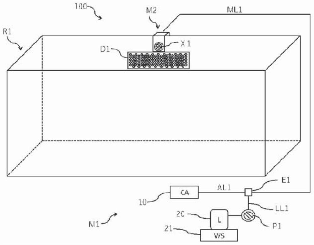
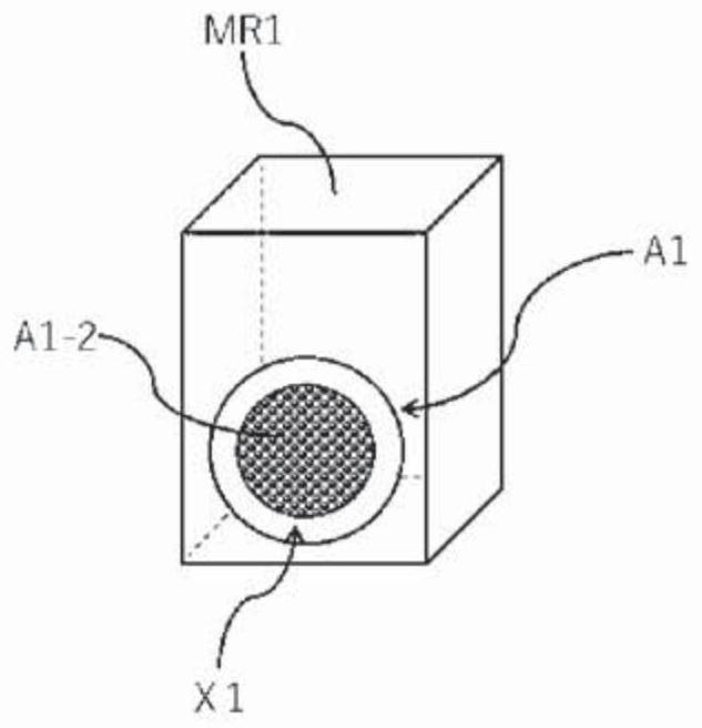
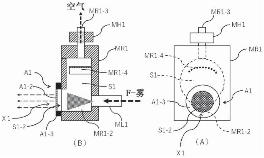
[0056] In the first embodiment of the present invention, a case where the purification system of the present invention is arranged in a purification target room of one room will be described. In addition, in the first embodiment, the primary mist generating unit and the secondary mist generating unit are used together as the hydrogen peroxide mist generating unit, and the finely atomized secondary mist is delivered to the purification target room as the purification mist. Internal release case.
[0057] figure 1 It is a schematic block diagram which shows the 1st Embodiment of the purification system of this invention. exist figure 1 , put an isolator (volume: 4m 3 ) is set as a purification target room, and a set of hydrogen peroxide mist generators (in this first embodiment, a combination of a primary mist generator and a secondary mist generator) emits the mist for purification. In addition, devices inside the isolator, such as a circulation fan, a HEPA filter, a rectif...
no. 2 approach 》
[0107] In the second embodiment, a case where the purification system of the present invention is arranged in a purification target room of one room, as in the above-described first embodiment, will be described. In addition, in this 2nd Embodiment, the case where only a single mist generating unit is used as a hydrogen peroxide mist generating unit is demonstrated, and the fine mist is discharged|emitted inside the purification object room as purification mist.
[0108] In the second embodiment, the secondary mist generating device M2 (including the ultrasonic atomizing device A1 ) used in the first embodiment is not used, and the hydrogen peroxide liquid is directly atomized and released into the purification target chamber. Therefore, it is preferable to reduce the particle diameter of the generated mist. In addition, as a mist generator, what is necessary is just to make a liquid hydrogen peroxide liquid into a fine mist, and the structure may be arbitrary.
[0109] For e...
no. 3 approach 》
[0122] In the third embodiment, a case where the purification system of the present invention is arranged in a purification target room having a large volume is described. Furthermore, in the third embodiment of the present invention, it will be described how to use one primary mist generating unit and two secondary mist generating units together as the hydrogen peroxide mist generating unit, and to use the finely atomized secondary mist as the purification mist. When two places are released into the interior of the purification target room.
[0123] Figure 7 (A) plan view which shows the schematic block diagram of the 3rd Embodiment of the purification system of this invention. and, Figure 8 It is a front view of (B) of a schematic structural drawing, and shows the state of the room|chamber interior by a partial fracture line. same, Figure 9 It is a (C) side view of a schematic structural diagram, and the state of the room|chamber interior is shown by the partial fract...
PUM
| Property | Measurement | Unit |
|---|---|---|
| The inside diameter of | aaaaa | aaaaa |
Abstract
Description
Claims
Application Information
 - R&D Engineer
- R&D Manager
- IP Professional
- Industry Leading Data Capabilities
- Powerful AI technology
- Patent DNA Extraction
Browse by: Latest US Patents, China's latest patents, Technical Efficacy Thesaurus, Application Domain, Technology Topic, Popular Technical Reports.
© 2024 PatSnap. All rights reserved.Legal|Privacy policy|Modern Slavery Act Transparency Statement|Sitemap|About US| Contact US: help@patsnap.com