Command center terminal hot standby method, device and system

A command center and terminal equipment technology, applied in the field of command center terminal backup, can solve problems such as seamless switching, system downtime, inability to ensure system security and stable operation, and achieve the effect of increasing branching and improving reliability.

Pending Publication Date: 2022-06-07
SHENZHEN AOTO ELECTRONICS
View PDF0 Cites 0 Cited by
  • Summary
  • Abstract
  • Description
  • Claims
  • Application Information

AI Technical Summary

Problems solved by technology

Therefore, there are more and more demands for command centers that have information aggregation, command decision-making, and situation analysis and judgment. Traditional command center projects often use analog signals to realize the access of various signals. This method controls, operates, maintains, The system docking is relatively cumbersome, so a distributed system is produced
The distributed system solves the access problem of various analog signals, making operation, maintenance, control and system docking easier, but at the same time, the distributed system also brings new problems, that is, high delay
In order to solve the problem of high delay, the optical fiber integrated terminal is applied to the command center project. The system architecture of the optical fiber integrated terminal belongs to the star architecture, which requires extremely high reliability of the integrated terminal. Once the terminal fails, it will cause The entire system is down, which seriously threatens the normal use of the system
The current optical fiber integrated terminal cannot perform real-time backup and seamless switching, and cannot guarantee the safe and stable operation of the entire system in an application scenario such as a command center that requires extremely high equipment reliability.
Once the optical fiber integrated terminal is down, the entire audio and video signals, control signals, data signals, etc. will not be transmitted, which will have a great impact on the system

Method used


Image

  • Command center terminal hot standby method, device and system
  • Command center terminal hot standby method, device and system
  • Command center terminal hot standby method, device and system

Examples


Embodiment Construction

[0058] In order to more clearly understand the above objects, features and advantages of the present invention, the present invention will be described in detail below with reference to the accompanying drawings and specific embodiments. It should be noted that the embodiments of the present application and the features of the embodiments may be combined with each other unless there is conflict. Unless otherwise defined, all technical and scientific terms used herein have the same meaning as commonly understood by one of ordinary skill in the art to which this invention belongs. The terms used herein in the description of the present invention are for the purpose of describing specific embodiments only, and are not intended to limit the present invention.

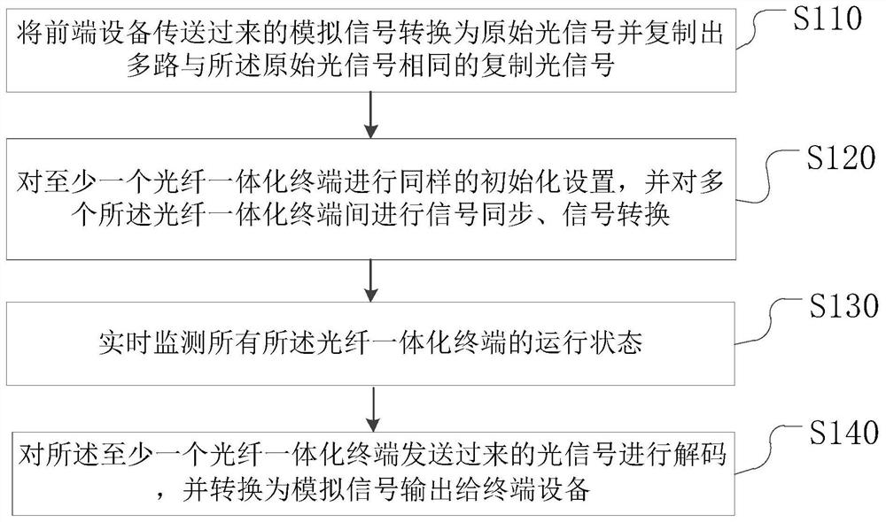
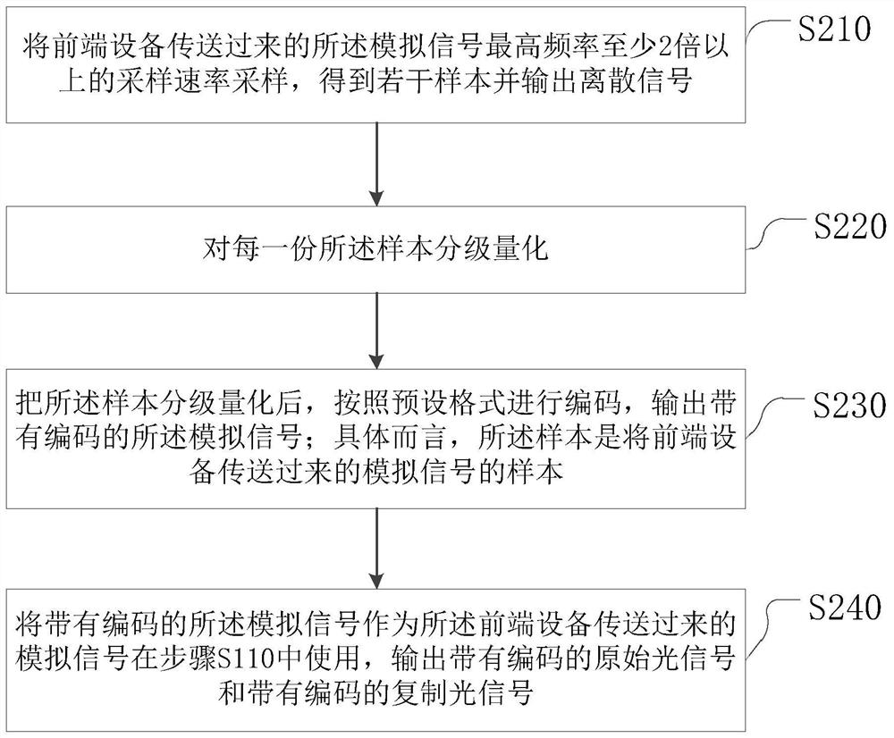
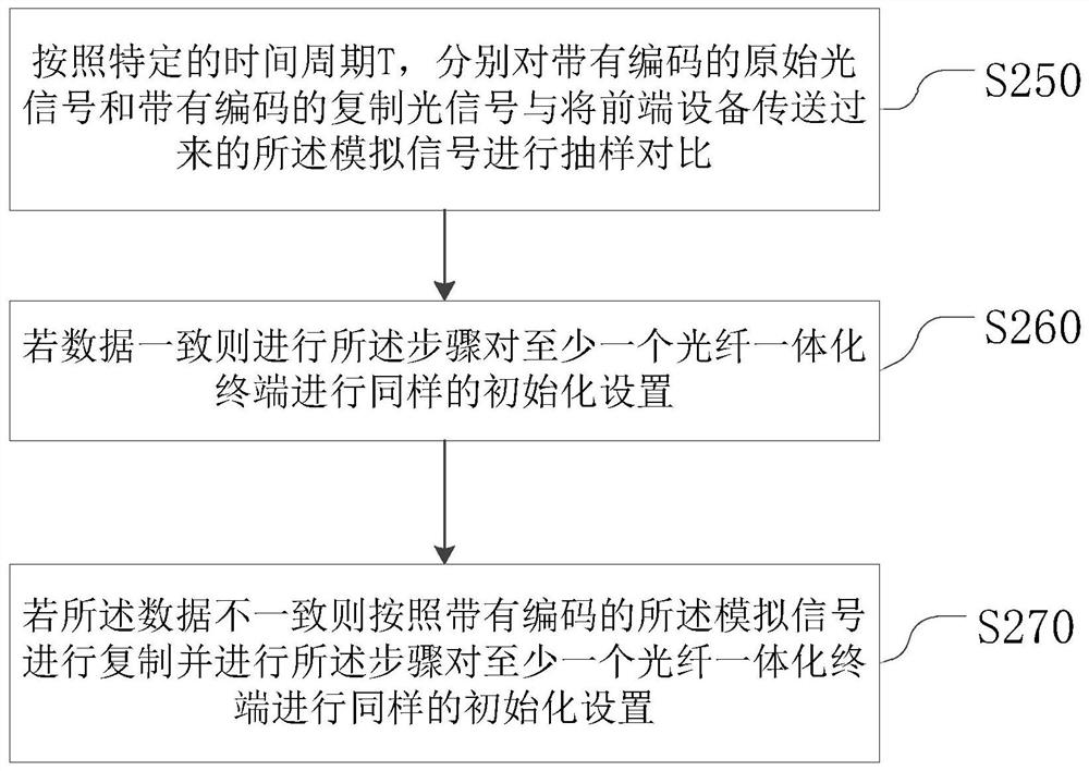
[0059] see figure 1 , figure 1 This is a flowchart of a command center terminal hot backup method according to an embodiment of the present invention; the command center terminal hot backup method includes:

[0060] Step...


PUM


Abstract

The invention relates to a command center terminal hot standby method, a command center terminal hot standby device and a command center terminal hot standby system. The command center terminal hot standby method comprises the following steps: converting an analog signal transmitted by front-end equipment into an original optical signal and copying multiple paths of copied optical signals which are the same as the original optical signal; carrying out the same initialization setting on at least one optical fiber integrated terminal, and carrying out signal synchronization and signal conversion on the plurality of optical fiber integrated terminals; monitoring the operation states of all the optical fiber integrated terminals in real time; and decoding the optical signal sent by the at least one optical fiber integrated terminal, converting the optical signal into an analog signal, and outputting the analog signal to terminal equipment. The system has the advantages that signal source shunting and merging and signal source synchronous control are added, real-time hot standby of the system is achieved, and the reliability of system operation is greatly improved.

Description

technical field [0001] The invention belongs to the technical field of command center terminal backup, and in particular relates to a command center terminal hot backup method, device and system. Background technique [0002] With the acceleration of urbanization in my country, a large number of people are gathering in cities, which has put high requirements on the comprehensive management capabilities of my country's management departments. Therefore, the command center has more and more needs for projects with information aggregation, command decision-making, and situation research and judgment. Traditional command center projects often use analog signals to realize the access of various signals. In this way, control, operation, maintenance, The system docking is relatively cumbersome, so a distributed system is produced. The distributed system solves the access problem of various analog signals, making operation, maintenance, control and system connection easier, but at ...

Claims


Application Information

Patent Timeline
IPC IPC(8): H04B10/03H04B10/032H04L41/0823H04L41/0631
CPCH04B10/03H04B10/032H04L41/0836H04L41/0631
Inventor 黄刚马煜程孙兴红吴振志吴涵渠
Owner SHENZHEN AOTO ELECTRONICS
Why Eureka
Try Eureka