Silt prevention method for silt-laden river wharf and silt-laden river wharf
A wharf and sediment technology, which is applied in the field of anti-silting of wharfs in rivers with many sediments, can solve problems such as easy deposition of sediment, adverse effects of navigation, and increased management costs
- Summary
- Abstract
- Description
- Claims
- Application Information
AI Technical Summary
Problems solved by technology
Method used
Image
Examples
Embodiment 1
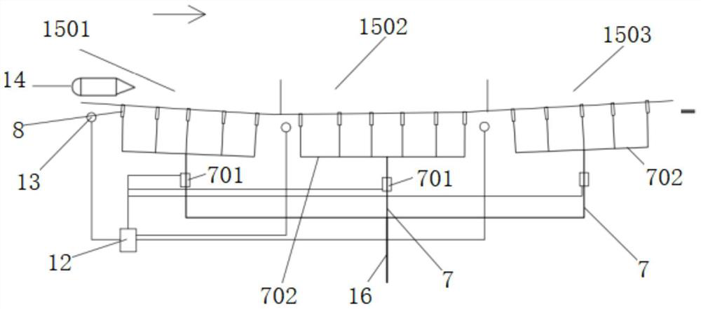
[0074] The embodiment of the present invention provides a silt prevention method for a river wharf with a lot of sediment, such as Figure 1-2 shown,
[0075] Include the following steps:
[0076] Step 1: A sensor 13 for sensing the ship 14 (which can be a sensor 13 for sensing the position of the ship 14, such as the sensor 13 for sensing the entry of the ship 14) and an anti-silt The nozzle 8, the anti-silt nozzle 8 is connected to the water supply system of the silt river wharf via the control valve 701, and the control valve 701 is connected to the control system 12 on the silt river wharf; The sensor 13 is installed at the start position of the top platform of the departure area 1503 at the lower part of the wharf, and several rows of anti-siltation nozzles 8 are arranged between 1.6m below the highest navigable water level and 1.6m below the lowest navigable water level, with an interval of 2m between each row. The nozzle is connected to the control valve 701, the wate...
Embodiment 2
[0086] On the basis of Example 1, as Image 6 As shown, the water supply system includes an auxiliary water supply device 3, and the auxiliary water supply device 3 includes:
[0087] The auxiliary box 31 is arranged on the dock base 1, and the auxiliary box 31 is provided with:
[0088] The first cylinder 32 is arranged at the inner upper end of the auxiliary box 31 . The first cylinder 32 is provided with a first piston 33 that slides up and down. The lower end of the first piston 33 is connected with a first piston rod 34 . The lower end of the first piston rod 34 slides through the lower end of the cylinder;
[0089] The second cylinder 35 is arranged on the right side of the first cylinder 32;
[0090] The second piston rod 36 slides through the right side of the first cylinder 32 and the left side of the second cylinder 35;
[0091] The second piston 37 is slidably connected to the second cylinder 35 left and right, the second piston 37 is fixedly connected to the sec...
Embodiment 3
[0113] On the basis of Example 2, as figure 2 As shown, the peripheral side of the first filter screen 316 is fixedly connected to the peripheral side inner wall of the first treatment tank 315 through elastic sealing members (such as elastic connecting belts). The first processing box 315 is located below the first filter screen 316, and the vibration box 4 is provided with: a second fixing block 41, and the upper end of the second fixing block 41 is connected with a second moving block 42 through a fifth spring 44 , the second moving block 42 is slidingly connected with the inner wall of the vibration box 4 up and down; the lower ends of the two first hinge rods 43 are hinged with the left and right parts of the second moving block 42 respectively, and the upper end of the first hinge rod 43 is hinged with a second hinge rod 43. A vibrating rod 45, the upper end of the first vibrating rod 45 penetrates above the vibrating box 4, and the first vibrating rod 45 is connected w...
PUM
 Abstract
Description
Claims
Application Information
 - Generate Ideas
- Intellectual Property
- Life Sciences
- Materials
- Tech Scout
- Unparalleled Data Quality
- Higher Quality Content
- 60% Fewer Hallucinations
Browse by: Latest US Patents, China's latest patents, Technical Efficacy Thesaurus, Application Domain, Technology Topic, Popular Technical Reports.
© 2025 PatSnap. All rights reserved.Legal|Privacy policy|Modern Slavery Act Transparency Statement|Sitemap|About US| Contact US: help@patsnap.com


