Sludge drying equipment for environmental pollution abatement

A technology for drying equipment and sludge, applied in the field of environmental pollution control, can solve the problems of reducing drying efficiency, increasing drying time, poor drying effect, etc., and achieving the effects of improving drying efficiency, improving uniformity, and avoiding stacking.

Pending Publication Date: 2022-06-07
冉坊
View PDF1 Cites 0 Cited by
  • Summary
  • Abstract
  • Description
  • Claims
  • Application Information

AI Technical Summary

Problems solved by technology

[0004] The purpose of the present invention is to solve the drying equipment in the prior art. During the drying process, the sludge is piled up on the drying plate, and then the sludge is heated by the heating equipment arranged under the drying plate, so that only the surface of the sludge can be heated. Drying will cause the moisture inside the sludge to remain in the sludge, resulting in poor drying effect, increasing the drying time, and reducing the drying efficiency. A kind of sludge drying equipment for environmental pollution control is proposed

Method used


Image

  • Sludge drying equipment for environmental pollution abatement
  • Sludge drying equipment for environmental pollution abatement
  • Sludge drying equipment for environmental pollution abatement

Examples


Embodiment 1

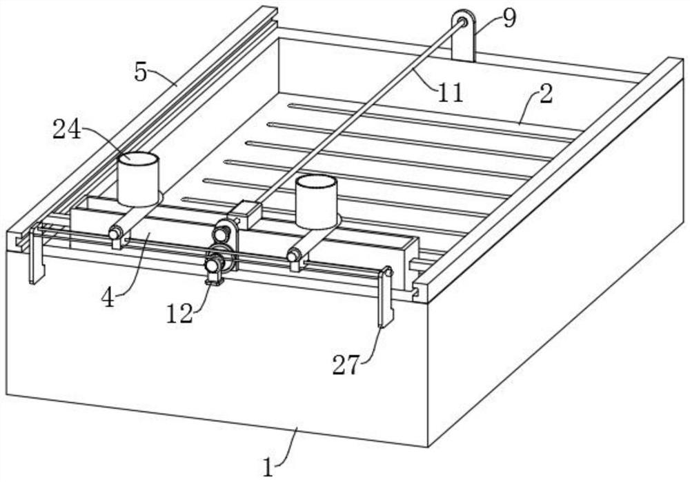
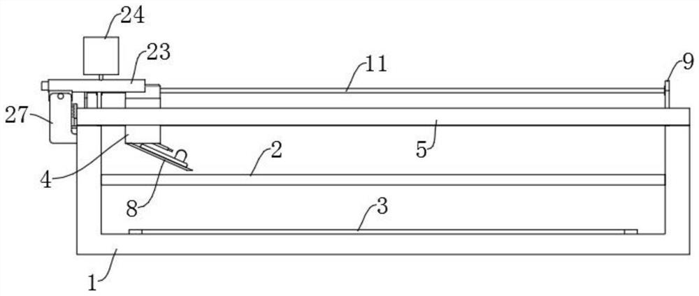
[0023] Reference Figure 1-4, a kind of environmental pollution control with silt drying equipment, including the box 1, the box 1 is fixed with a mesh plate 2, the bottom of the box 1 is fixed to install a number of equally spaced distribution of the heating plate 3, the top of the box 1 is provided with a transfer box 4, the top of the box 1 is fixed on both sides of the slide 5, the transfer box 4 is fixed on both sides of the slider 6, the slide 6 is set in the slide 5, the bottom of the transfer box 4 is equipped with an outlet 7, and the bottom of the transfer box 4 is fixed with a deflector plate 8. The bottom of the box 1 is fixedly installed with two spaced side plates 9, the top of the transfer box 4 is fixed with a top block 10, further comprising a drive mechanism, the drive mechanism is connected to the top block 10 and can drive the transfer box 4 along the slide 5. The drive mechanism comprises a first screw 11, the first screw 11 through the top block 10 and is conn...

Embodiment 2

[0026] Reference Figure 1-4 , as another preferred embodiment of the present invention, the difference with Example 1 is that the deflector plate 8 is provided with a accumulation mechanism, the accumulation mechanism is disposed on the upper end face of the deflector plate 8 and connected to the transfer box 4. The accumulation mechanism comprises two side baffles 15, two side baffles 15 are fixed on both sides of the upper end surface of the deflector plate 8, the side baffle 15 is fixed with a support plate 16, the two support plates 16 can be rotated between the mounted shaft 17, the lower baffle 18 is fixed on the hinge 17, the hinge 17 end runs through the support plate 16, the reel 17 end sleeve is provided with a reed 19, and the two ends of the reed 19 are fixed on the reel 17 and the support plate 16. The accumulation mechanism further comprises a positioning mechanism, the positioning mechanism is fixed at the end of the shaft 17. Positioning mechanism comprising a cyli...


PUM


Abstract

The invention relates to the technical field of environmental pollution abatement, in particular to sludge drying equipment for environmental pollution abatement, which comprises a box body, a screen plate fixedly mounted in the box body, a plurality of heating plates distributed at equal intervals fixedly mounted at the bottom in the box body, a transfer box arranged at the top of the box body, and slideways fixedly mounted on both sides of the top of the box body, sliding blocks are fixedly installed on the two sides of the transfer box and slidably arranged in the sliding ways correspondingly, an outlet is formed in the bottom of the transfer box, and a flow guide plate is fixedly installed at the bottom of the transfer box. Two side plates which are arranged at an interval are fixedly mounted at the bottom of the box body, a top block is fixedly mounted at the top of the transfer box, and the sludge drying device further comprises a driving mechanism, and sludge to be dried is placed in the transfer box, so that the sludge discharged from the flow guide plate can be uniformly laid on a net plate in the discharging process; and then the sludge on the net plate is dried through the multiple heating plates, the drying uniformity can be improved, the sludge is prevented from being stacked, the interior of the sludge can be rapidly dried, and the drying efficiency is improved.

Description

Technical field [0001] The present invention relates to the field of environmental pollution control technology, in particular to a kind of sludge drying equipment for environmental pollution control. Background [0002] In environmental management, it is necessary to clean up the silt in the river channel, and after cleaning, the silt is dried, and the dried silt can be used as nutrients. The existing application number is CN201820392378.4 a kind of sludge drying equipment for environmental pollution control, specifically disclosed: including the box, the first movable board, the second movable board, the electric push rod, the mixing shaft, the support sleeve, the hollow mixing rod, the crushing blade, the gear, the motor, the disc, the movable rod, the rack, the connecting rod, the swing rod, the rubber ball and the extractor,......., use waste heat to keep the box warm, avoid heat dissipation, while protecting the environment while avoiding affecting the health of the staff. ...

Claims


Application Information

Patent Timeline
IPC IPC(8): C02F11/13
CPCC02F11/13Y02W10/37
Inventor 冉坊
Owner 冉坊
Why Eureka
Try Eureka