Cable rack for electrical automation engineering construction and use method thereof
An electrical automation and engineering construction technology, applied in the direction of electrical components, cable installation, cable installation devices, etc., can solve problems such as difficulty in adjustment, universal influence, structural solidification, etc., to achieve convenient maintenance and replacement work, and flexible assembly and connection work. Effect
- Summary
- Abstract
- Description
- Claims
- Application Information
AI Technical Summary
Problems solved by technology
Method used
Image

Examples
Embodiment 1
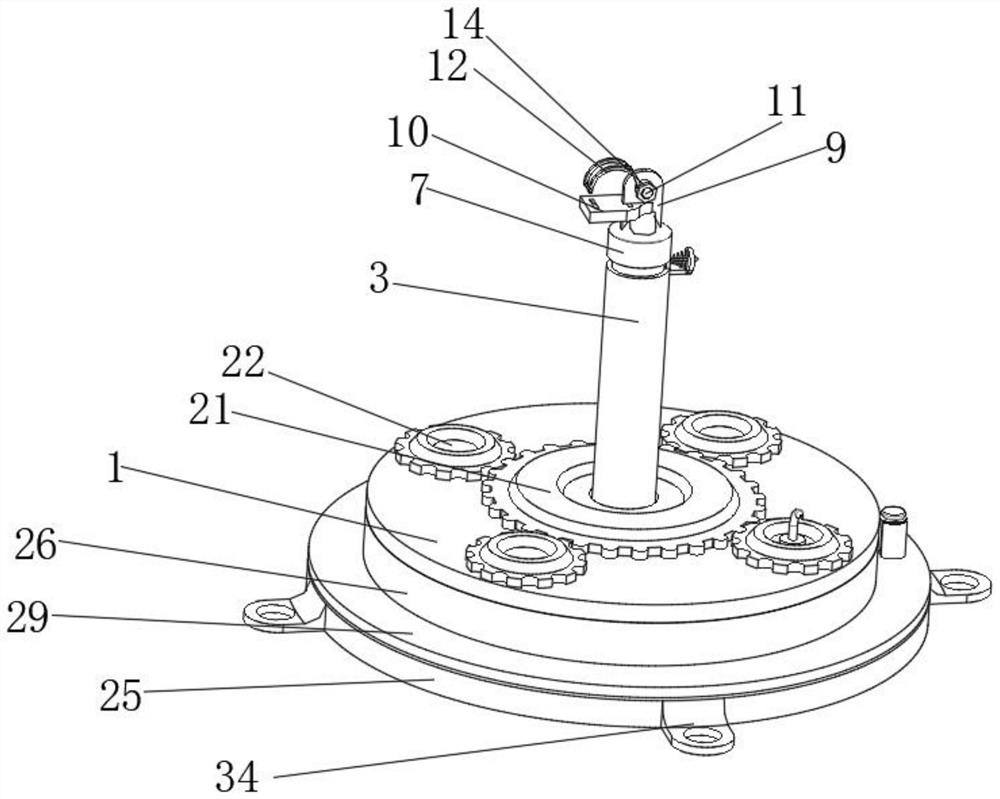
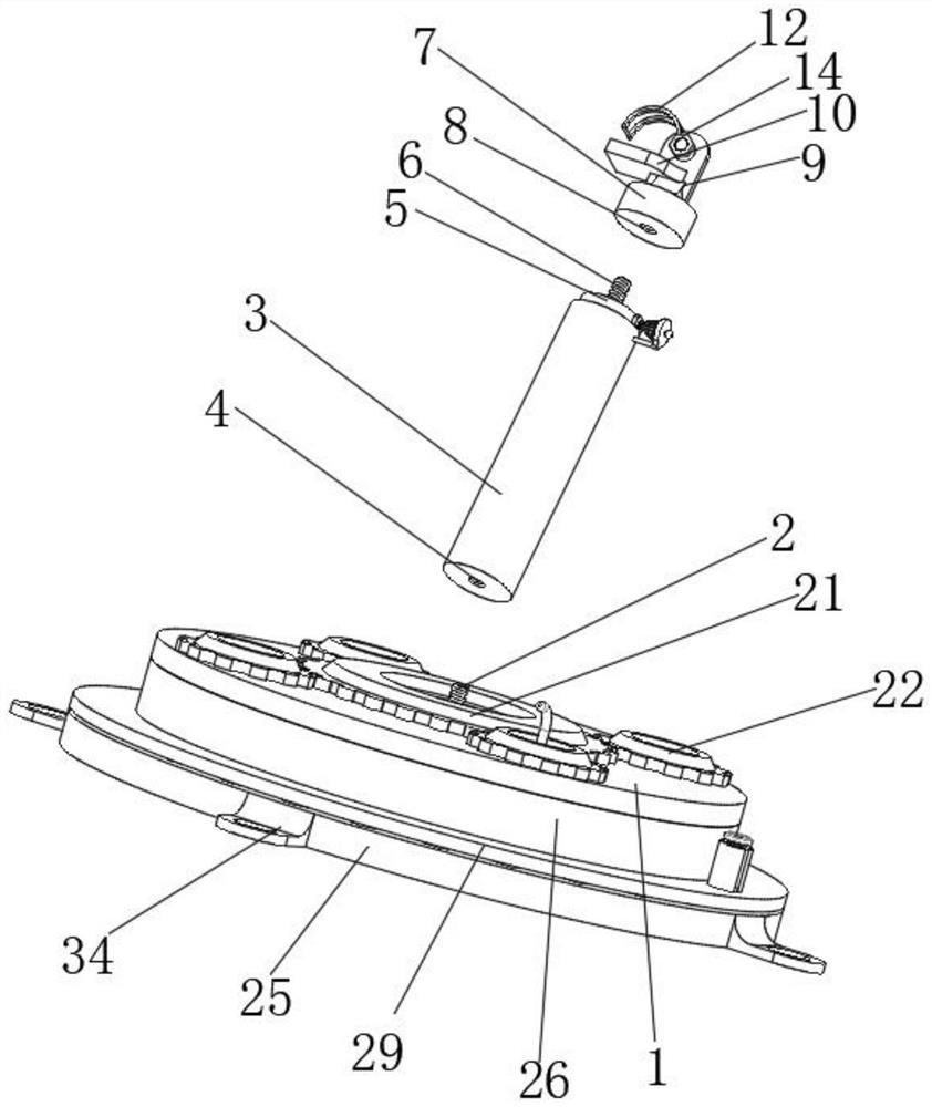
[0035] see Figure 1-3, the present invention provides a technical solution: a cable rack for electrical automation engineering construction, including a support plate 1, the center of the upper surface of the support plate 1 is equipped with a No. 1 screw 2, and the support plate 1 can provide stability for the No. 1 screw 2 Support, the upper surface of the No. 1 screw 2 is provided with a sleeve 3, the bottom end of the sleeve 3 is provided with a No. 1 screw hole 4, and the No. 1 screw hole 4 is rotatably connected with the No. 1 screw 2. The purpose of this design is to realize the sleeve For the disassembly and assembly function of the barrel 3, an extension rod 5 is slidably connected to the inner side of the sleeve 3. The movement track of the extension rod 5 can be limited by the sleeve rod 30, thereby realizing the telescopic function of the extension rod 5. The top of the extension rod 5 is equipped with The No. 2 screw 6, the upper surface of the extension rod 5 is...
Embodiment 2
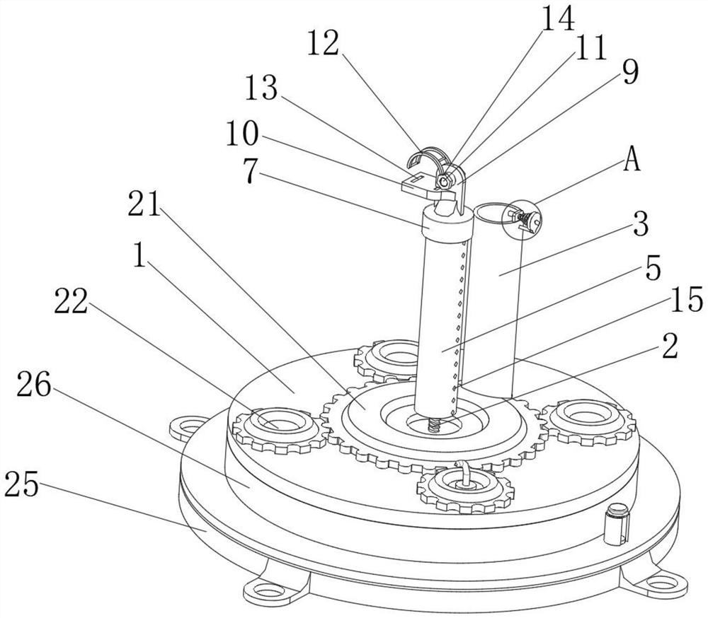
[0038] see Figure 4 , the upper surface of the support plate 1 is rotatably connected with a central gear 21 and a driving gear 22, and the central gear 21 and the driving gear 22 are meshed. This design is to realize the linkage function between the driving gear 22 and the central gear 21. A handle is installed on the surface, which can provide convenience for the rotation of the driving gear 22. The central position of the lower surface of the driving gear 22 is equipped with a threaded rod 23. During the rotation of the driving gear 22, the threaded rod 23 also rotates, and the threaded rod 23 also rotates. One end of 23 runs through the lower surface of the support plate 1, the lower surface of the support plate 1 is equipped with a round rod 24, the lower surface of the support plate 1 is provided with a base 25, the upper surface of the base 25 is rotatably connected with a turntable 26, and the upper surface of the turntable 26 A threaded hole 27 and a circular hole 28...
Embodiment 3
[0040] see Figure 5 and 7 , the outer surface of the turntable 26 is equipped with a ring frame 29, the ring frame 29 also rotates during the rotation of the turntable 26, the inner side of the ring frame 29 is equipped with a sleeve rod 30, and the inner side of the sleeve rod 30 is slidably connected with a locking rod 31 and the gripping rod 32, the gripping rod 32 is fixedly connected with the locking rod 31, during the movement of the gripping rod 32, the locking rod 31 also moves along with it. The moving track is fixed, the upper surface of the base 25 is provided with a locking hole 33, and the locking hole 33 is sleeved on the outer surface of the locking rod 31. The angle is fixed, the outer surface of the base 25 is equipped with a mounting plate 34, the upper surface of the mounting plate 34 is provided with a mounting hole, and bolts are driven into the inner side of the mounting hole to realize the position fixing function of the mounting plate 34, and then the...
PUM
 Abstract
Description
Claims
Application Information
 - R&D
- Intellectual Property
- Life Sciences
- Materials
- Tech Scout
- Unparalleled Data Quality
- Higher Quality Content
- 60% Fewer Hallucinations
Browse by: Latest US Patents, China's latest patents, Technical Efficacy Thesaurus, Application Domain, Technology Topic, Popular Technical Reports.
© 2025 PatSnap. All rights reserved.Legal|Privacy policy|Modern Slavery Act Transparency Statement|Sitemap|About US| Contact US: help@patsnap.com